Industrial motors, transformers, and other inductive loads consume reactive power, increasing the current drawn from electrical distribution systems. A low power factor can lead to higher distribution losses, reduced available system capacity, and additional utility charges.
Power factor correction (PFC) reduces upstream reactive power demand, helping industrial facilities use their electrical infrastructure more effectively.
This guide explains how power factor correction works, common compensation methods, capacitor sizing formulas, and how to select suitable equipment for industrial applications.
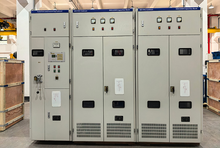
LTECPower medium-voltage power factor correction cabinets
1. What Is Power Factor Correction?
Power factor correction improves an electrical system’s power factor by reducing the reactive power demand on the upstream supply.
Power factor is the ratio of real power (kW) to apparent power (kVA). A value closer to 1 means you need less apparent power to deliver the same real power.
In industrial AC systems, capacitors commonly provide reactive power locally to offset inductive demand from motors and transformers. Depending on load conditions, compensation may use fixed capacitor banks, automatic power factor correction (APFC) systems, or dynamic reactive power equipment.
2. Why Is Power Factor Correction Important?
A low power factor increases the apparent power (kVA) and current required to deliver the same real power (kW). Proper power factor correction can provide several benefits for industrial electrical systems.
Reduce Current and Power Losses
Improving power factor reduces upstream current demand, helping lower I²R losses in cables and transformers.
Increase Available System Capacity
Lower current demand can free up capacity in existing transformers, cables, and switchgear, potentially allowing additional loads without immediate equipment upgrades.
Reduce Electricity Costs
Some utilities impose penalties for low power factor or charge for reactive energy and apparent power demand. Power factor correction may reduce these costs, depending on the electricity tariff.
Support Voltage Stability
Supplying reactive power closer to inductive loads can reduce reactive current flow through upstream network impedance and help support voltage under suitable operating conditions.
Power factor correction does not directly reduce the useful energy required by equipment. Its main benefits come from reducing upstream reactive power demand, distribution losses, and potential utility charges.
3. How Does Power Factor Correction Work?
Power factor correction works by supplying reactive power locally to offset the inductive reactive power demand of equipment such as motors and transformers.
Without compensation, the upstream supply must provide both real power (kW) and reactive power (kvar), increasing apparent power (kVA) and current demand.
When connected in parallel with an electrical system, shunt capacitors supply capacitive reactive power locally, reducing the reactive power drawn from the upstream supply.
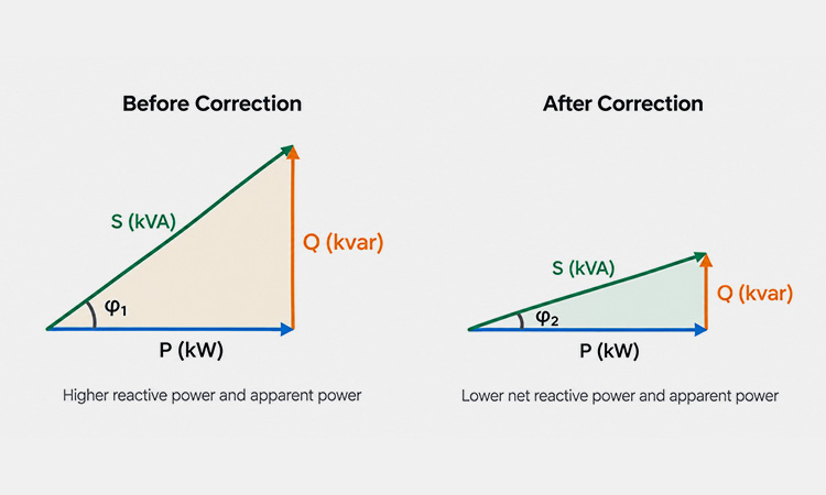
Power factor correction reduces reactive power and apparent power while maintaining real power
Understanding the Power Triangle
The power triangle illustrates the relationship between:
Real Power (P, kW): Power used to perform useful work.
Reactive Power (Q, kvar): Power associated with energy exchanged between the supply and reactive components.
Apparent Power (S, kVA): The combined effect of real and reactive power.
For sinusoidal voltage and current:
\[ S=\sqrt{P^2+Q^2} \]
\[ PF=\frac{P}{S} \]
After correction, the capacitor bank reduces net reactive power demand, bringing the power factor closer to unity.
However, excessive compensation can cause a leading power factor, while systems with significant harmonic distortion require additional evaluation.
4. Power Factor Correction Methods
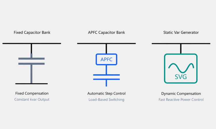
Different power factor correction methods are used depending on load characteristics and reactive power demand. Common industrial solutions include fixed capacitor banks, automatic power factor correction systems, and dynamic reactive power compensation.
Fixed Capacitor Banks
Fixed capacitor banks provide a constant amount of reactive power compensation when energized. They are suitable for relatively stable inductive loads but may cause overcompensation during light-load operation.
For medium-voltage applications, MV capacitor banks can provide reactive power compensation when properly designed for the electrical system.
Automatic Power Factor Correction (APFC)
Automatic power factor correction systems use a controller to switch capacitor bank steps according to changing reactive power demand.
They are commonly used in industrial facilities with variable loads, helping maintain the target power factor without excessive compensation.
Dynamic Reactive Power Compensation
Dynamic solutions, such as Static Var Generators (SVGs), provide fast, continuously adjustable reactive power compensation using power electronics.
They are suitable for rapidly fluctuating loads that require faster response or more precise compensation than conventional mechanically switched capacitor banks.
The appropriate method depends on load variation, response time, system voltage, and harmonic conditions.
Power factor correction methods comparison
Method
Load Conditions
Compensation Type
Fixed Capacitor Banks
Stable loads
Fixed compensation
APFC Capacitor Banks
Variable loads
Automatically switched steps
Static Var Generators (SVGs)
Rapidly fluctuating loads
Fast, continuously adjustable compensation
5. Power Factor Correction Formula and Calculation
The required capacitor bank size can be estimated using the load’s real power, existing power factor, and target power factor. This calculation helps engineers determine the capacitive reactive power (kvar) needed to improve power factor.
Power Factor Correction Formula
For a sinusoidal system with an inductive load, the required reactive power compensation is:
\[ Q_c=P(\tan\varphi_1-\tan\varphi_2) \]
Where:
Qc (kvar): Required capacitive reactive power compensation
P (kW): Real power of the load
φ₁: Power factor angle before correction
φ₂: Target power factor angle after correction
The power factor angles can be calculated using:
\[ \varphi=\cos^{-1}(PF) \]
Power Factor Correction Calculation Example
Consider an industrial load with the following operating conditions:
Real power: 100 kW
Existing power factor: 0.75
Target power factor: 0.95
Step 1: Calculate the power factor angles.
\[ \varphi_1=\cos^{-1}(0.75)\approx41.41^\circ \]
\[ \varphi_2=\cos^{-1}(0.95)\approx18.19^\circ \]
Step 2: Calculate the required compensation.
\[ Q_c=100(\tan41.41^\circ-\tan18.19^\circ) \]
\[ Q_c\approx55.3\text{ kvar} \]
The estimated compensation requirement is approximately 55 kvar.
This calculation provides an initial sizing reference, not a final capacitor bank specification. Actual selection must consider operating voltage, load variation, harmonic conditions, and available capacitor steps.
Why Correct Capacitor Sizing Matters
Undersized capacitor banks may fail to achieve the target power factor, while oversized banks can cause overcompensation during low-load operation.
Variable loads may require automatic compensation, and systems with significant harmonics should be evaluated for resonance risks before capacitor installation.
6. Power Factor Correction Equipment
Industrial power factor correction equipment typically includes capacitors, switching and control devices, and protective components. The configuration depends on system voltage, reactive power demand, and harmonic conditions.
Power Factor Correction Capacitors
LTECPower low-voltage power capacitors
Power factor correction capacitors supply capacitive reactive power to offset inductive loads. They are available for low- and medium-voltage systems and can be installed individually or combined into capacitor banks.
Capacitor Banks and Automatic Power Factor Correction (APFC)
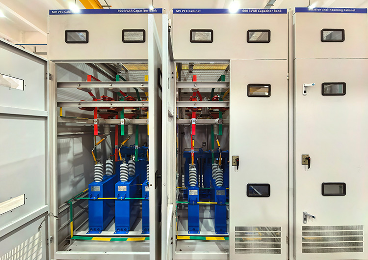
LTECPower medium-voltage power factor correction cabinets
Capacitor banks combine multiple capacitor units to achieve the required kvar capacity. In automatic power factor correction (APFC) systems, controllers monitor power factor or reactive power demand and switch capacitor steps as needed to maintain the target power factor.
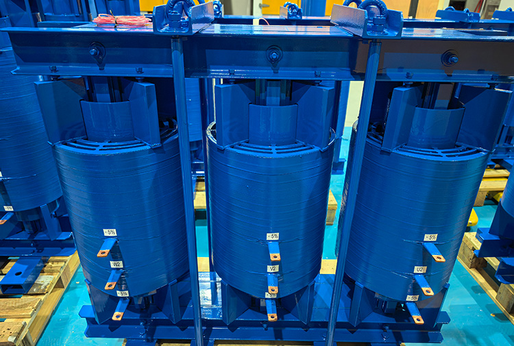
Detuned Reactors
LTECPower-three-phase detuned reactor
Detuned reactors are connected in series with capacitors to shift the compensation branch’s tuning frequency and reduce the risk of harmonic resonance.
They do not eliminate all harmonics, and their selection should consider the system’s harmonic spectrum and electrical ratings.
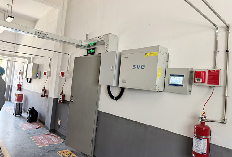
Static Var Generators (SVGs)
LTECPower wall-mounted static var generator (SVG)
Static Var Generators (SVGs) use power electronics to provide continuously adjustable reactive power compensation.
They are particularly useful in systems with rapidly changing reactive power demand.
Equipment selection should consider the complete electrical system rather than capacitor capacity alone.
7. How to Choose the Right Power Factor Correction Solution
Selecting the right power factor correction solution requires evaluating system conditions rather than capacitor capacity alone.
System Voltage and Required kvar
Confirm the system voltage, frequency, existing power factor, and target power factor. Use measured load data to calculate the required compensation capacity in kvar.
Load Variation and Response Time
Fixed capacitor banks suit stable loads, while APFC systems adjust compensation for changing demand. Rapidly fluctuating loads may require SVGs or fast-switched capacitor systems.
Harmonic Distortion and Resonance
Evaluate systems with VFDs, rectifiers, or other nonlinear loads for harmonic distortion and resonance risks.
Where appropriate, detuned reactors can reduce resonance risks, while harmonic filters may be needed to control distortion.
Protection and Installation
Consider capacitor switching transients, inrush current, discharge requirements, and protective device coordination. Ambient temperature, ventilation, and installation space also affect equipment reliability.
A properly designed system should maintain the required power factor without introducing unacceptable overcompensation, resonance, or switching problems.
8. Common Power Factor Correction Mistakes
Incorrect power factor correction design can cause overcompensation, harmonic resonance, and equipment reliability problems. The following mistakes should be avoided.
Oversizing Capacitor Banks
Excessive capacitor capacity can cause a leading power factor, particularly during light-load operation. Compensation should be based on measured reactive power demand and the required power factor range.
Ignoring Harmonic Resonance
Capacitor banks may interact with system inductance and amplify existing harmonics. Facilities with significant nonlinear loads should assess resonance risks before installation and consider appropriately designed detuned reactors where necessary.
Using Fixed Compensation for Variable Loads
Fixed capacitor banks may provide too much or too little compensation as loads change. APFC systems or dynamic compensation equipment can offer better control under variable operating conditions.
Neglecting Switching and Protection
Improper switching devices, inadequate inrush current control, or insufficient discharge arrangements can compromise capacitor bank reliability. Appropriate protection and switching design are essential for safe operation.
Avoiding these mistakes helps maintain effective compensation and reliable electrical system performance.
Conclusion
Power factor correction helps industrial facilities reduce reactive power demand, improve electrical system capacity, and potentially lower utility charges. Effective compensation requires proper sizing, harmonic assessment, and equipment selection.
LTECPower manufactures low- and medium-voltage power capacitors, reactors, and power quality equipment for industrial applications.
Contact LTECPower to discuss your system voltage, target power factor, and reactive power compensation requirements.
Frequently Asked Questions About Power Factor Correction
What Is Power Factor Correction in Electrical Systems?
Power factor correction (PFC) improves an electrical system’s power factor by reducing upstream reactive power demand. Capacitor banks are commonly used to compensate for inductive loads such as motors and transformers.
How Do You Calculate Power Factor Correction?
Use the formula Qc = P × (tan φ₁ − tan φ₂), where P is real power in kW and φ₁ and φ₂ are the existing and target power factor angles. The result is the required compensation in kVAR.
Which Capacitor Is Used for Power Factor Correction?
AC power capacitors designed for reactive power compensation are commonly used. Depending on voltage and capacity requirements, they may be installed individually or combined into low- or medium-voltage capacitor banks.
What Is Automatic Power Factor Correction (APFC)?
Automatic power factor correction uses a controller to switch capacitor bank steps according to changing reactive power demand. It helps maintain the target power factor in electrical systems with variable loads.
Can Power Factor Correction Cause Harmonic Problems?
Yes. Capacitor banks can interact with system inductance and create harmonic resonance. Systems with significant nonlinear loads may require harmonic studies and appropriately designed detuned reactors.
Does Power Factor Correction Reduce Electricity Bills?
Power factor correction may reduce electricity bills where utilities charge for low power factor, reactive energy, or apparent power demand. Actual savings depend on the tariff structure and operating conditions.
Struggling with transformer overheating or power quality issues? Discover the root causes of electrical harmonics, how non-linear loads distort waveforms, and explore advanced mitigation solutions—including active filters, detuned reactors, and VPI-insulated transformers—to protect your industrial infrastructure.
Learn how filter reactors protect PFC capacitors from harmful harmonics, prevent thermal overload, and stabilize power grids. Read our full technical guide now.
Struggling to choose between passive and active harmonic filters? This comprehensive engineering guide breaks down core differences, real-world application scenarios, IEEE-519 compliance, and total cost of ownership to help industrial buyers make the right choice.