A shunt capacitor is a capacitor connected in parallel with an electrical power system to supply capacitive reactive power. Shunt capacitors are widely used for power factor correction and voltage support in industrial distribution networks and substations.
But how do shunt capacitors work, where are they installed, and what should engineers consider before using them? This guide explains their working principle, key applications, and practical selection considerations.
1. What Is a Shunt Capacitor?
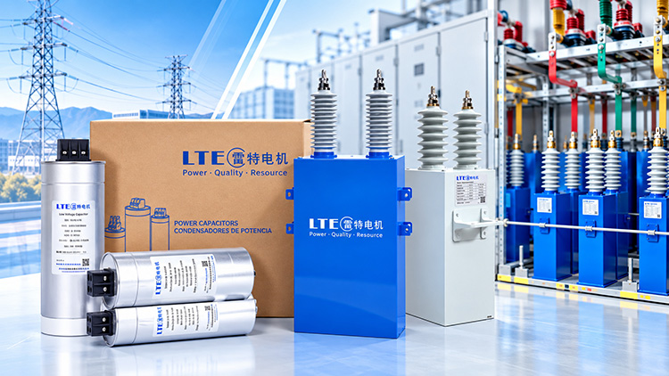
LTECPower shunt capacitors for industrial power factor correction and reactive power compensation.
A shunt capacitor is a power capacitor connected in parallel with an electrical load or busbar to provide capacitive reactive power. It is commonly used in AC power systems to compensate for inductive loads, such as motors and transformers, helping improve power factor and support system voltage.
In practice, shunt capacitors are often installed as capacitor banks, which combine multiple capacitor units to achieve the required reactive power rating (kvar or Mvar). Depending on system requirements, the MV capacitor banks may be fixed or automatically switched to match changing reactive power demand.
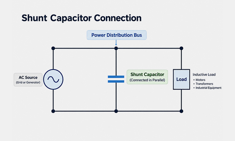
Simplified diagram showing a shunt capacitor connected in parallel with an electrical load.
Unlike a series capacitor, which is connected directly in the current path, a shunt capacitor operates as a parallel branch of the electrical system.
2. How Does a Shunt Capacitor Work?
Most industrial power systems contain inductive loads, such as motors and transformers, that require reactive power to operate. Without local compensation, part of this reactive power must be supplied through the upstream electrical network.
A shunt capacitor works by supplying capacitive reactive power at the point where it is connected. This offsets part of the inductive reactive power demand, helping improve the power factor and reduce reactive current drawn from the upstream supply. Shunt capacitors are one of several technologies used in industrial power quality solutions to manage reactive power and improve electrical system performance.
As a result, properly sized shunt capacitors can reduce upstream current, lower associated distribution losses, and support system voltage under suitable operating conditions.
Shunt Capacitor Reactive Power Formula
For a balanced three-phase capacitor bank, the total capacitive reactive power is:
Qc = 3 × 2πf × Cph × Vph²
Where:
Qc = total three-phase capacitive reactive power (var)
f = system frequency (Hz)
Cph = capacitance per phase (F)
Vph = RMS voltage across each capacitor phase (V)
For a wye-connected bank, phase voltage is the line-to-neutral voltage. For a delta-connected bank, each capacitor phase is subjected to the line-to-line voltage.
The reactive power output increases with capacitance and with the square of the applied voltage, making correct capacitor bank sizing essential.
3. What Are Shunt Capacitors Used For?
Shunt capacitors are primarily used for reactive power compensation, power factor correction, and voltage support in AC power systems. When properly sized and installed, they can provide several practical benefits:
Improve Power Factor
Shunt capacitors compensate for inductive reactive power demand from equipment such as motors and transformers, helping improve the power factor seen by the upstream supply.
Reduce Reactive Current and Distribution Losses
By supplying reactive power closer to the load, shunt capacitors can reduce upstream current and associated I²R losses in cables and transformers.
Support System Voltage
In suitable operating conditions, shunt capacitors help maintain voltage levels by supplying capacitive reactive power, particularly in networks with significant inductive demand.
Reduce Reactive Power Charges
Where electricity tariffs include power factor penalties or reactive energy charges, correctly applied shunt capacitors may help reduce these costs.
However, capacitor banks must be properly sized and controlled. Excessive compensation can lead to a leading power factor, overvoltage, or other operating problems.
4. Shunt Capacitors in Distribution Systems and Substations
Shunt capacitors are used in industrial distribution networks, utility substations, and transmission systems to provide reactive power compensation and voltage support. Their installation location and configuration depend on the system voltage, load characteristics, and compensation requirements.
Industrial Distribution Systems
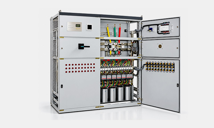
Shunt capacitor bank for industrial power factor correction.
In industrial facilities, shunt capacitor banks are commonly installed at main distribution panels, motor control centers, or near large inductive loads. Low-voltage power capacitors can provide centralized or local power factor correction, helping reduce reactive current in the upstream distribution network.
Medium-Voltage Distribution and Substations
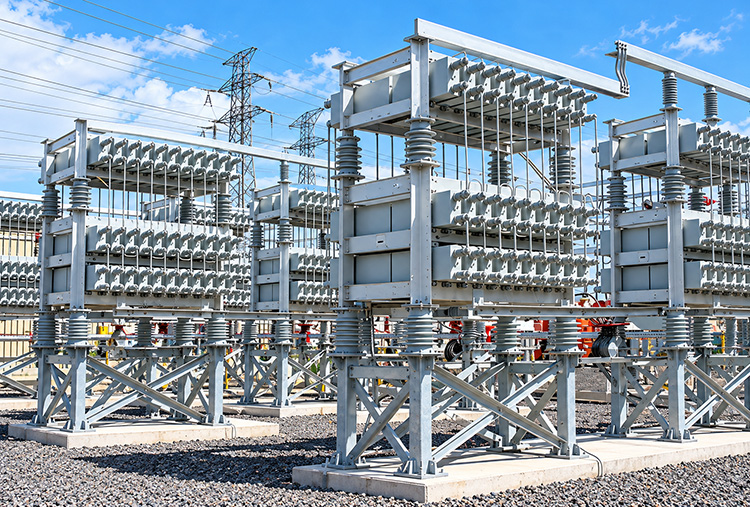
Shunt capacitor banks for MV reactive power compensation.
In medium-voltage networks and substations, shunt capacitor banks are typically connected to distribution buses or dedicated feeders. Medium-voltage capacitors are used in these applications to provide reactive power support and help manage voltage profiles.
Transmission Systems
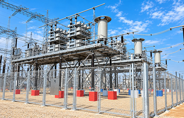
High-voltage substation equipment supporting power transmission.
Shunt capacitor banks may also be installed at transmission substations to provide capacitive reactive power and support voltage during suitable operating conditions. Their application requires careful consideration of system voltage, switching operations, and network conditions.
System studies should determine the appropriate capacitor bank arrangement, considering load variation, voltage limits, harmonics, and switching requirements.
5. Series vs. Shunt Capacitors: What's the Difference?
The main difference between series and shunt capacitors is how they are connected to the power system and what they are designed to achieve.
Shunt capacitors are connected in parallel with a bus or load. They supply capacitive reactive power to support voltage and improve power factor, making them common in industrial distribution networks and substations.
Series capacitors, on the other hand, are installed in series with transmission lines to compensate for part of the line’s inductive reactance. This can improve power transfer capability and influence voltage regulation.
Both technologies use capacitors, but they serve different purposes and are not interchangeable.
Feature
Shunt Capacitors
Series Capacitors
Connection
Parallel to the bus or load
Series with the line
Main Purpose
Reactive power compensation
Series reactance compensation
Typical Benefits
Power factor correction, voltage support
Improved power transfer capability
Common Applications
Industrial distribution, substations
Transmission networks
System Effect
Supplies capacitive reactive power at the connection point
6. What Should Engineers Consider Before Installing Shunt Capacitors?
Selecting a shunt capacitor bank involves more than choosing a kVAR rating. Engineers must consider the electrical system, load variations, harmonic conditions, and protection requirements to ensure safe and reliable operation.
Before installation, review these six factors:
System Voltage and Frequency
Confirm the nominal system voltage, operating voltage range, and frequency (50/60 Hz). Capacitor voltage ratings and insulation requirements must match the installation conditions.
Required Reactive Power (kvar)
Determine the compensation needed based on measured load demand and the target power factor. Oversizing can cause overcompensation, particularly during light-load operation.
Harmonic Distortion and Resonance
Capacitors can interact with system inductance and create resonance conditions that amplify harmonic distortion. Systems with significant nonlinear loads may require harmonic studies and detuned reactors designed to mitigate them.
Fixed vs. Switched Capacitor Banks
Fixed banks suit relatively stable reactive power demand, while automatically switched banks can adjust compensation as operating conditions change.
Switching and Protection
Evaluate switching transients, inrush current, discharge requirements, overcurrent protection, and capacitor bank protection coordination.
Installation Conditions
Consider ambient temperature, ventilation, altitude, available space, and indoor or outdoor installation requirements.
A properly selected shunt capacitor bank should deliver the required reactive power compensation without introducing unacceptable voltage, harmonic, or switching problems.
Conclusion
Shunt capacitors play an important role in reactive power compensation, power factor correction, and voltage support across industrial and utility power systems.
However, effective compensation depends on more than capacitor capacity alone. System voltage, load variation, harmonic conditions, and switching requirements must all be considered to ensure reliable operation.
At LTECPower, we manufacture low- and medium-voltage power capacitors for industrial and power distribution applications. Explore our capacitor products or contact our team to discuss your system voltage, required kvar rating, and application requirements.
Frequently Asked Questions About Shunt Capacitors
What Is the Difference Between a Shunt Capacitor and a Capacitor Bank?
A shunt capacitor is a capacitor connected in parallel with an electrical system to provide capacitive reactive power. A capacitor bank consists of multiple capacitor units connected to achieve the required reactive power rating. A shunt capacitor bank is therefore a capacitor bank used for parallel compensation.
Can Shunt Capacitors Improve Power Factor?
Yes. Shunt capacitors supply capacitive reactive power that offsets part of the reactive power demand of inductive loads. This can improve the power factor measured by the upstream supply. However, excessive compensation may produce a leading power factor, especially during periods of low load.
What Is the Difference Between Fixed and Switched Shunt Capacitors?
Fixed shunt capacitor banks remain connected during their intended operating periods and are generally suited to relatively stable reactive power demand. Switched capacitor banks can connect or disconnect capacitor steps as system conditions change, helping maintain more appropriate compensation under varying loads.
What Is the Difference Between a Shunt Reactor and a Shunt Capacitor?
A shunt capacitor supplies capacitive reactive power, while a shunt reactor absorbs reactive power. Shunt capacitors are commonly used to compensate for inductive loads and support voltage. Shunt reactors are often used to absorb excess reactive power and help control overvoltage, particularly in lightly loaded networks.
Can Shunt Capacitors Cause Harmonic Resonance?
Yes. Shunt capacitors can interact with system inductance and create resonance conditions near existing harmonic frequencies. This may amplify harmonic currents or voltages and place additional stress on electrical equipment. Harmonic studies and properly designed detuned reactor arrangements may be necessary in systems with significant nonlinear loads.
Where Are Shunt Capacitor Banks Typically Installed?
Shunt capacitor banks may be installed at industrial distribution panels, near large inductive loads, on medium-voltage distribution buses, or in utility substations. The appropriate location depends on the required reactive power compensation, voltage level, load characteristics, and system operating conditions.
Learn how filter reactors protect PFC capacitors from harmful harmonics, prevent thermal overload, and stabilize power grids. Read our full technical guide now.
Struggling with transformer sizing, power factor penalties, or VFD harmonic stress? This comprehensive engineering guide breaks down VA/kVA calculations, VPI manufacturing benefits, and essential design standards for industrial facilities.
Navigate VFD harmonic challenges with confidence. This guide compares AC Line Reactors and Harmonic Filter Reactors, helping you lower THDi and choose the right component to keep your operations running safely.