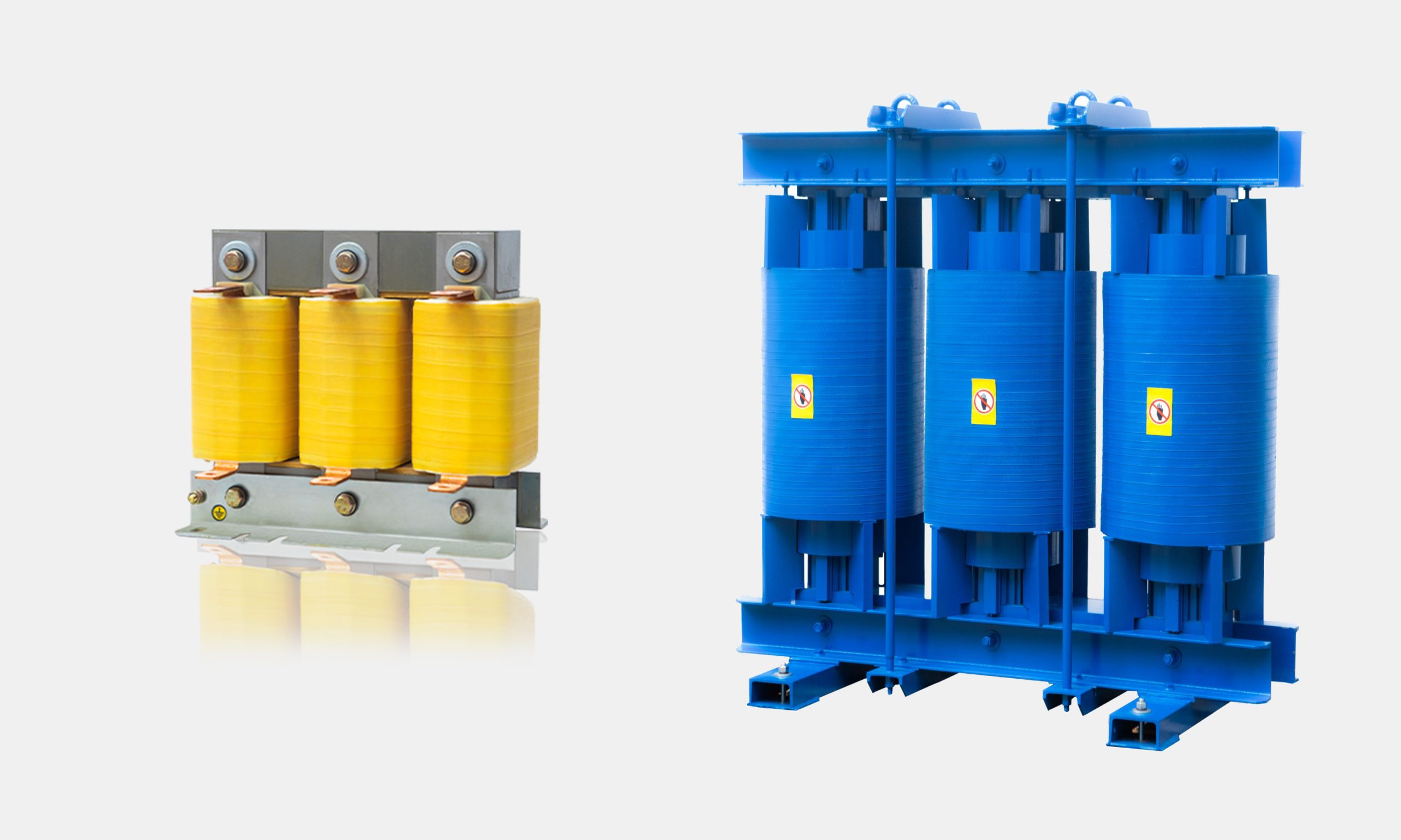
LTECPowr Filter Reactors
In modern industrial plants, variable speed drives (VSDs) and automation always improve your efficiency, but they also introduce harmful electrical harmonics.
However, the harmonics will bring invisible distortions that may lead to equipment stress, overheating, and costly unplanned downtime.
To safeguard your power grid against hidden harmonics, we help you with this technical guide. You can explore how filter reactors protect your assets, ease grid stress, and ensure system stability.
Whether you are designing a new PFC panel or searching for a custom filter reactor manufacturer, this guide provides the exact engineering criteria to protect your capacitors and stabilize your grid
1. What are harmonics, and why are they considered the “high blood pressure” of industrial power systems?
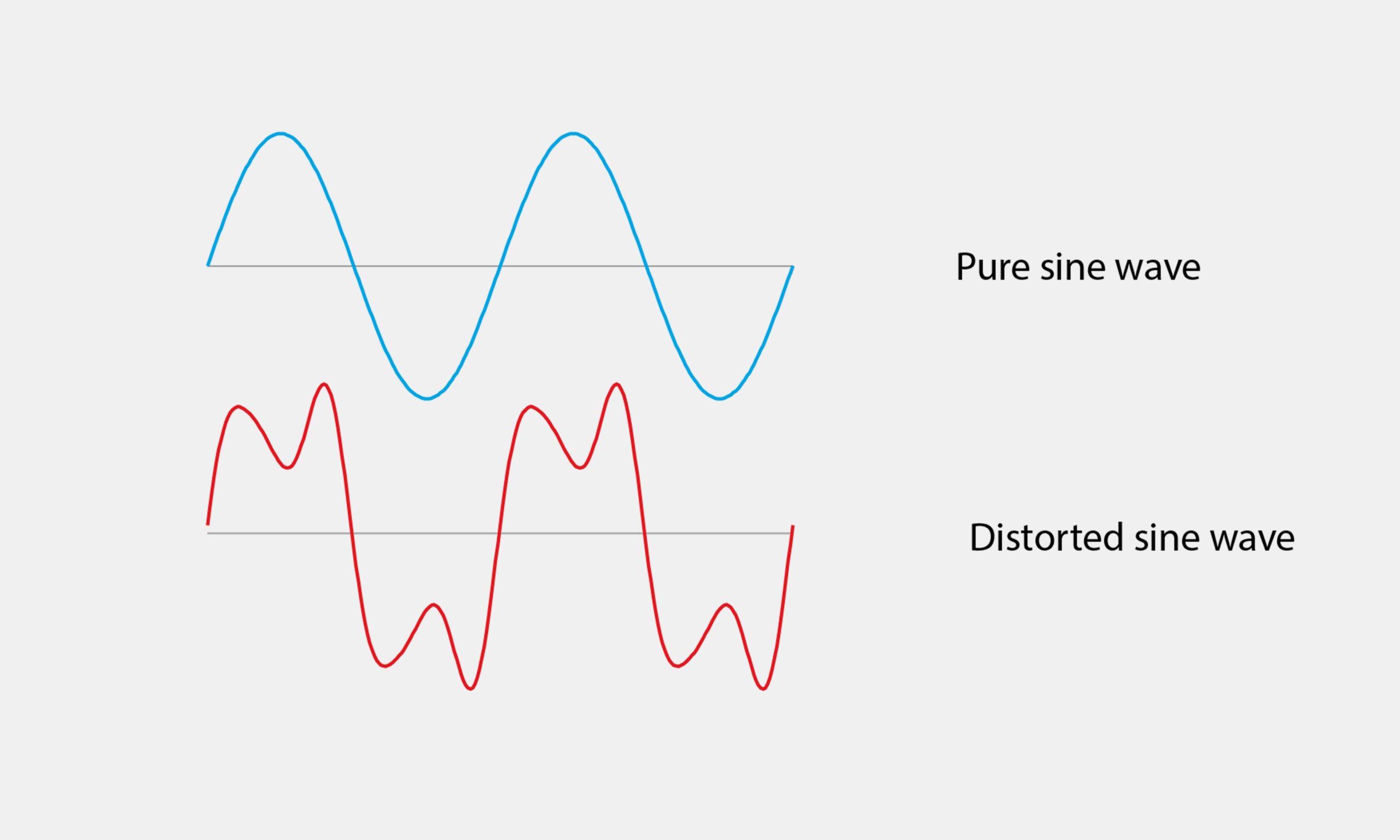
Pure sine wave vs. harmonic distortion waveform. (Source: Hioki)
A healthy electrical grid always operates with a clean waveform at a fundamental frequency (typically 50 Hz or 60 Hz) under normal conditions.
However, non-linear loads—such as AC/DC motor drives, uninterruptible power supplies (UPS), and switch-mode power supplies—are prone to producing distorted voltage and current waveforms.
So, the harmonics are brought into your grids.
Harmonics: High Blood Pressure?
Yes, harmonics are much like high blood pressure in the human body. Because they often bring your “body” inefficiencies, overheating, or sudden equipment failure.
Once exceeding the limits, there will be severe hazards for the whole distribution system.
2. What exactly is a harmonic filter reactor, and how does it differ from a standard line reactor?
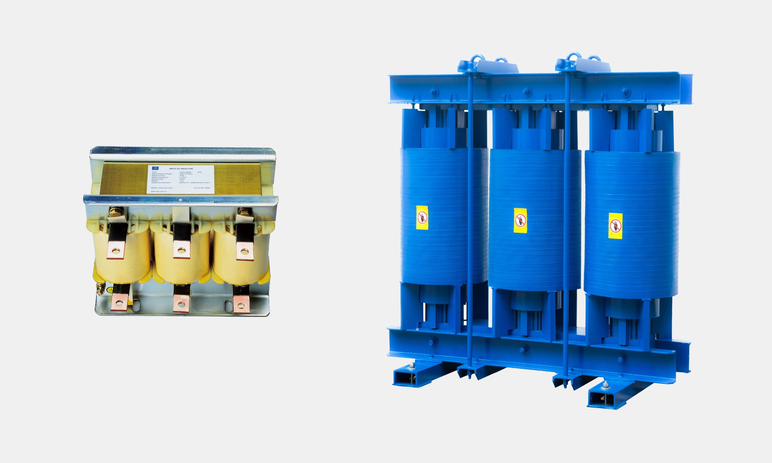
LTECPower Line Reactor vs. Detuned Filter Reactor
Frequently called a detuned reactor, the filter reactor is a specialized power quality equipment connected in series with power factor correction (PFC) capacitor banks.
Acting as a reliable guardian for your electrical systems, the harmonic filter reactor can absorb the stress to keep your plant safe, efficient, and resilient.
Filter Reactor VS Line Reactor
Typically placed on the input of a drive, the line reactor can suppress transient spikes and line notches. However, specially designed to work with capacitors, the filter reactor can manage reactive power while blocking or trapping specific harmonic frequencies.
3. What are the risks of using PFC capacitor banks without a filter reactor?
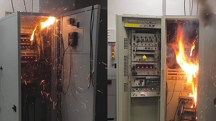
Catastrophic fire hazard (Source: workplacepub)
In today’s non-linear industrial grids, running PFC capacitors without filter reactors may lead to catastrophic hardware damage and cause you costly downtime.
Capacitor Failure and Fire Hazards
High-frequency harmonics from VFDs and rectifiers may overheat your capacitors and greatly shorten capacitor service life by up to 80%. Even more, the thermal stress will lead to oil leakage, swelling, and violent internal short circuits.
Harmonic Resonance Catastrophe
Without a reactor, your capacitor and transformer will align with the 5th or 7th harmonics. Causing a resonance loop, it may create voltage surges up to 2–3 times the rated limit. Then, your capacitor banks will end up with unexpected factory shutdowns.
Unexpected Factory Downtime
If the harmonics are left untreated and flow back, it will cause you severe cable overheating, distribution transformer power loss, and random breaker trips.
4. How does a filter reactor form a detuned circuit with capacitors to shift resonant frequencies?
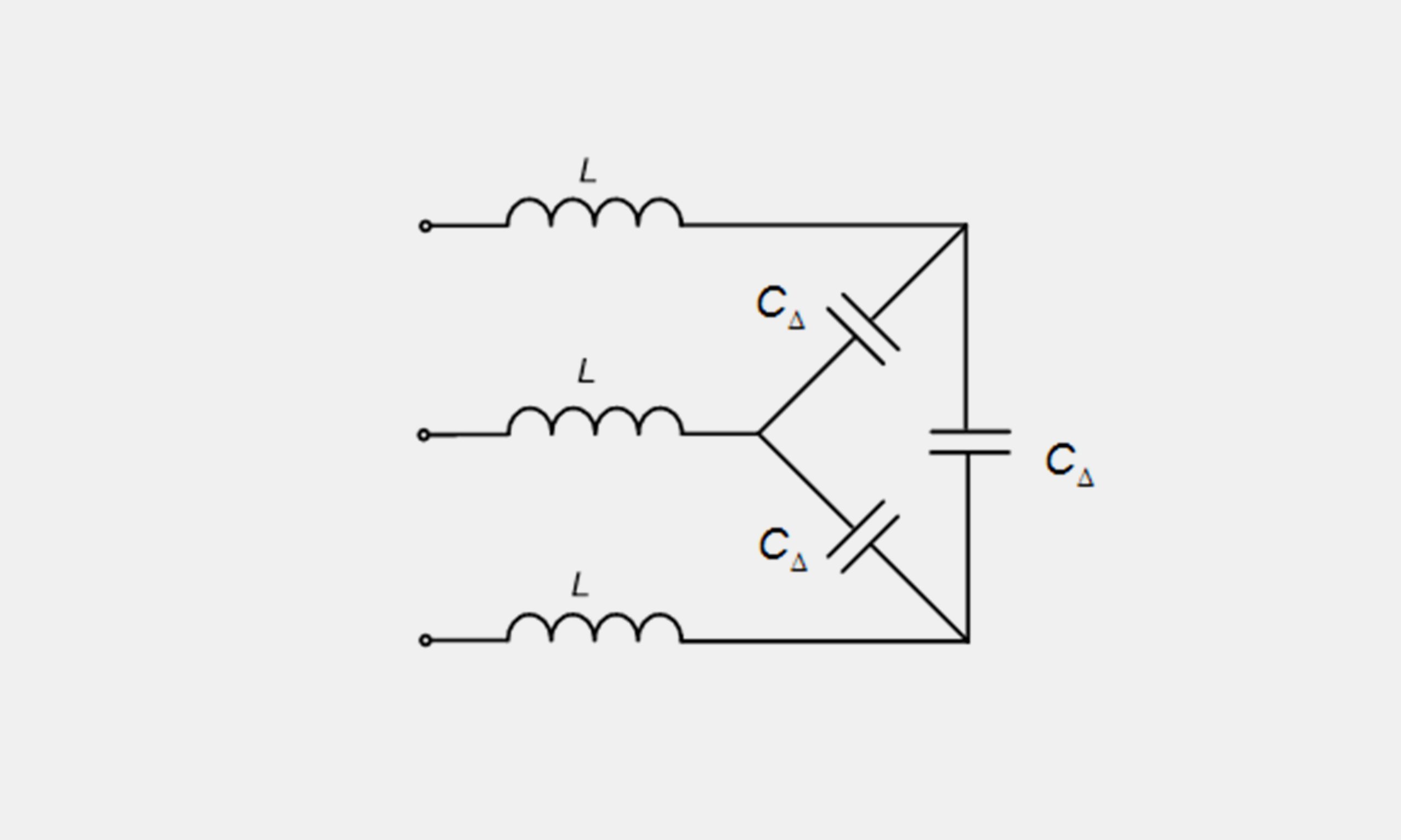
Circuit Topology (Source: researchgate)
Working as a frequency shield for your PFC capacitors, once installed in series, the filter reactor will form an LC circuit precisely with the capacitor.
Precision Tuning
Applied in a 50 Hz grid with heavy 5th harmonic distortion (250 Hz), a 7% detuned reactor can handle the natural resonance frequency down to 189 Hz (or 134 Hz for 14% reactors).
Inductive Shielding
In a 50/60 Hz grid, filter reactors with a capacitor remain capacitive to correct the power factor. However, to all high-frequency harmonics, they turn inductive, preventing harmonic resonance and current amplification.
5. What role do precision multi-air gaps and high-permeability cores play in filter reactors?
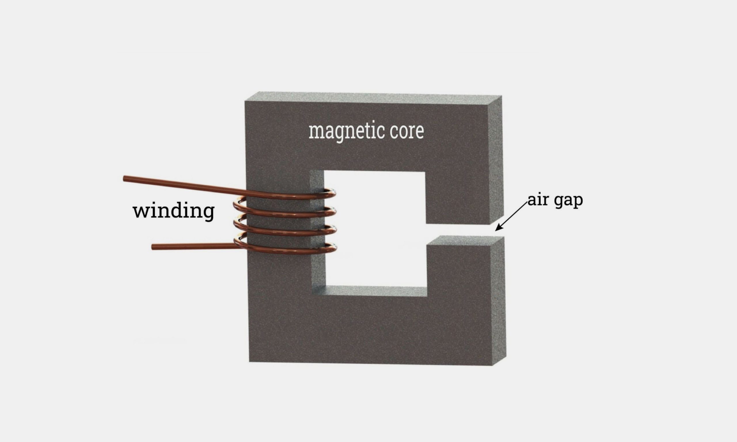
Principle of Core Air Gap (Source: iqsdirectory)
As the “heart” of a filter reactor, the magnetic core is specially engineered to eliminate reactor failures, overheating, and excessive humming caused by magnetic saturation.
Anti-Saturation Linearity
Our high-permeability silicon steel is designed with multiple small air gaps, so it can avoid sudden inductance loss if there are harmonic power surges.
Vibration and Noise Reduction
Every unit of our filter reactors is built with Vacuum Pressure Impregnation (VPI). Building laminations and windings into a vibration-proof solid, so they can dampen operational noise to under 65 dB.
6. When should you specify a 5.67% (210 Hz) detuning factor versus a standard 7% (189 Hz) reactor?
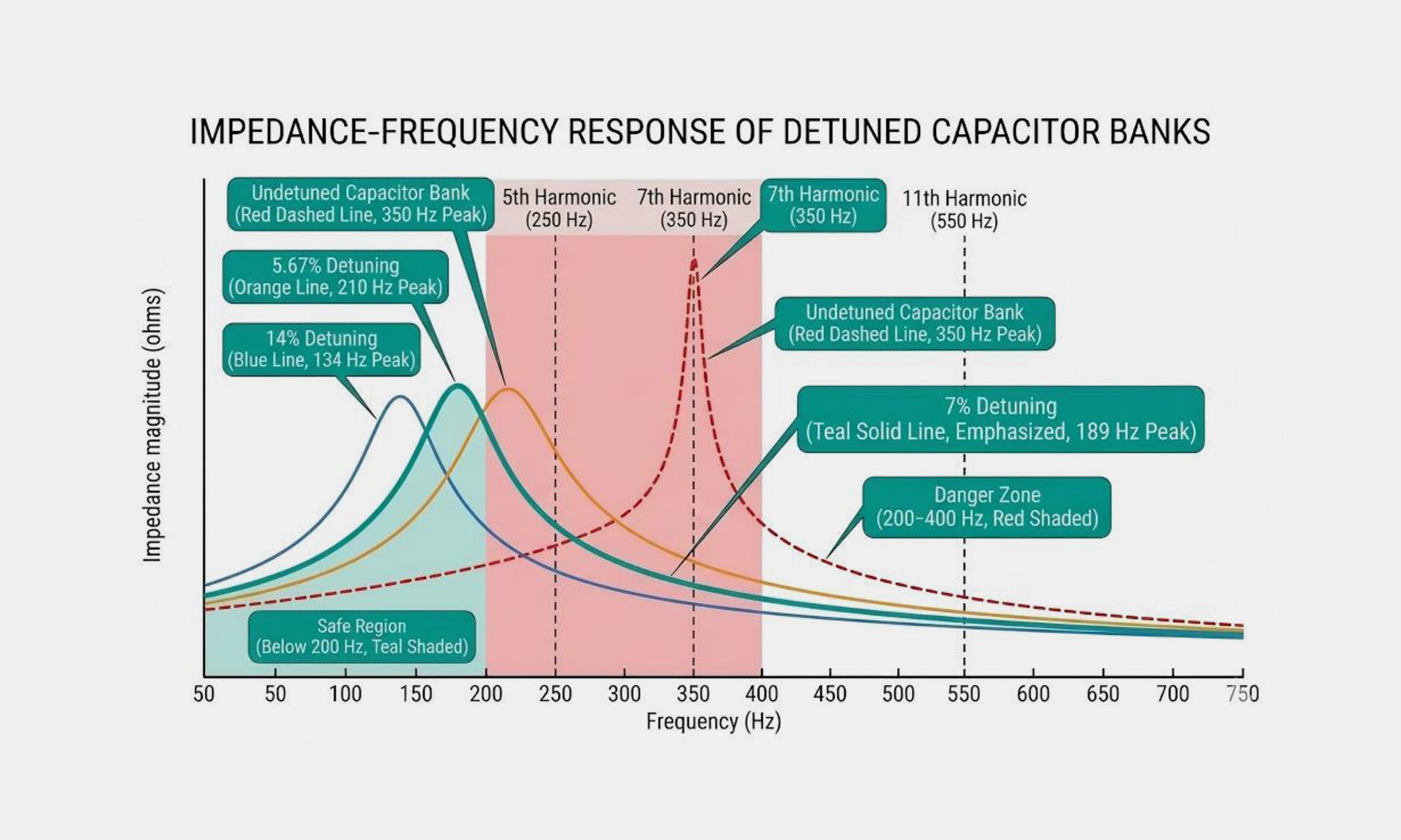
Impedance-Frequency Curve (Source: xbrele)
The detuning factor (p%) is determined by your system harmonics.
p = 5.67% (fr = 210 Hz on 50 Hz systems)
The 5.67% detuning reactor is built to manage a slightly tighter reactive compensation profile. They can keep the resonance point safely below the 5th harmonic.
p = 7% (fr = 189 Hz on 50 Hz systems)
As the global industrial standard type, the 7% detuning reactor is perfect for power systems heavily impacted by 5th, 7th, and 11th harmonics. They can keep your network safe and reactive power output balanced.
7. Why and when is a 14% (134 Hz ) high-impedance detuned reactor required in heavy harmonic environments?
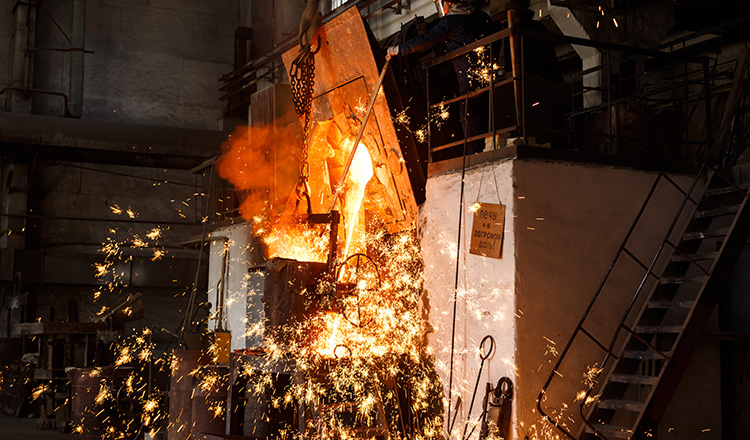
Heavy Harmonic Applications
For extremely harsh electrical environments with severe low-order harmonics, the 14% detuned reactor is an ultimate defense line.
When Do You Need a 14% Reactor?
Severe 3rd Harmonic: It is necessary for heavy single-phase non-linear loads, arc furnaces, steel mills, and medium-frequency induction heaters in 3-phase 4-wire systems to install a 14% detuned reactor.
High Total Harmonic Voltage Distortion: If the THDu> 8%, then the 7% reactor is not enough for thermal overload.
How 134 Hz Detuning Protects Your System
Pushing your system’s resonant frequency down to 134 Hz, the 14% reactor can block harmonic resonance and keep your grid stable.
8. What does “linearity” mean for a filter reactor, and why is a linearity of 1.73 * rms or 200% critical during overcurrent spikes?
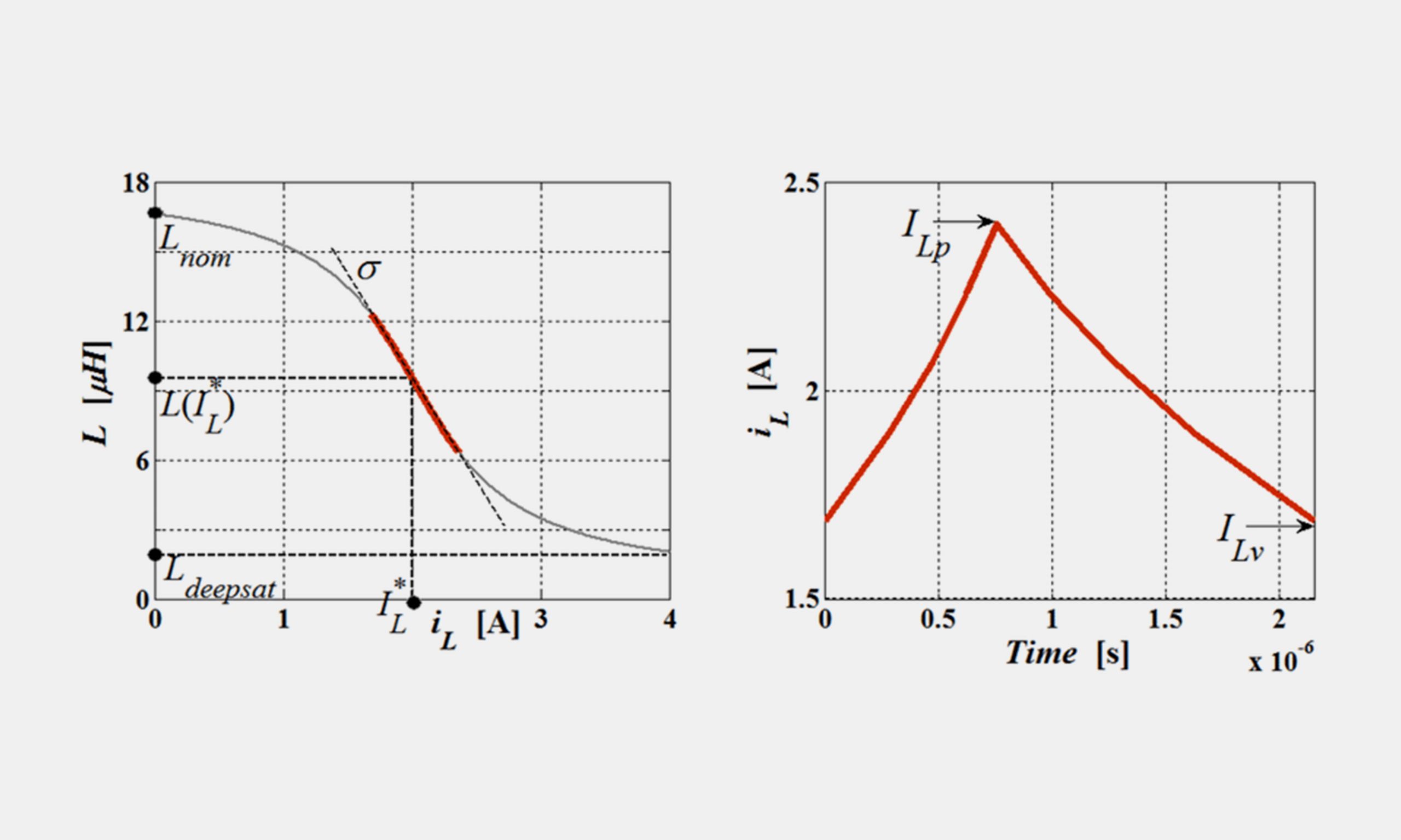
Inductance-Current Linearity Curve (Sourced: researchgate)
Linearity means the reactor’s resistance to magnetic overload. Under normal running current, standard reactors can perform well. However, if there are many severe transient spikes in your factory, the standard type is not enough.
1.73 * rms Linearity and 200% Surge Cushion
To survive heavy industrial operation, your reactors must be constructed with a high saturation threshold. The 1.73 * rms ensures your reactor at least 95% nominal inductance even when there are continuous harmonic currents and overloads. Locked solidly in place, the 200% surge cushion can prevent dangerous frequency drift during switching surges.
9. Copper vs. Aluminum Windings in Filter Reactors: How do they impact efficiency, weight, and thermal lifespan?
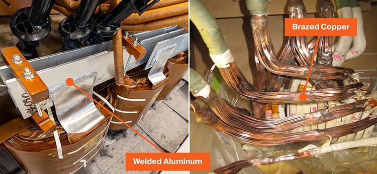
Winding Material & Jointing (Sourced: maddox)
Choosing between Copper and Aluminium windings sometimes difficult. Because it may impact your machinery cost, operating energy losses, and cabinet space requirements. However, we can give you answers.
Comparison: Making Your Right Choice
| Performance | Copper (Cu) Windings | Aluminum (Al) Windings |
| Initial Purchase Cost | Higher | Lower (15–25% Savings) |
| Long-Term Energy Losses | Lower (Higher Efficiency) | Slightly Higher |
| Equipment Size & Footprint | Compact (20–30% Smaller) | Larger (Requires More Space) |
| Total Equipment Weight | Heavier | Significantly Lighter |
| Best Application Match | Space-constrained cabinets, Data Centers, High-efficiency facilities | Large-scale factory panels, Commercial buildings, Tender-driven budget projects |
10. Why are Class H Insulation (180 ℃) and Vacuum Pressure Impregnation (VPI) critical for filter reactor longevity?
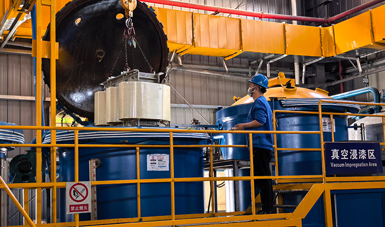
LTECPower In-House VPI
In a power factor correction system, harmonic currents will bring you non-stop heat accumulation. The thermal stress will harm the insulation quality. In the end, your reactor will fail in 20 months.
Class H (180 ℃) vs. Class F (155℃): The +25°C Safety Cushion
In an electrical system, every 10℃ reduction in operating temperature doubles your thermal life of insulation materials. Most budget reactors are built with Class F (155℃) standards, not sufficient for clean, nominal loads.
If you upgrade to Class H, then you may get +25℃ extra thermal buffer. So, even under severe harmonic spikes or ambient temperature rises, your reactor can still operate well for 20 years.
VPI (Vacuum Pressure Impregnation) vs. Standard Dip Varnish
| Feature | LTEC Class H VPI Reactor | Standard Dip-Varnished Reactor |
| Insulation Thermal Class | Class H (180 ℃) | Class F (155℃) |
| Thermal Safety Margin | +25°C extra cushion | Minimal or zero margin |
| Resin Penetration | 100% void‑free (vacuum + pressure) | Surface‑level coating with air pockets |
| Dielectric Breakdown Risk | Virtually eliminated (zero PD) | High risk of turn‑to‑turn short circuits |
| Environmental Protection | Resistant to moisture, salt spray, and chemicals | Prone to moisture ingress and core oxidation |
Why This Difference Matters:
| Feature | LTEC Class H VPI Reactor Advantage | Our Value |
| Insulation Thermal Class | Class H (180 ℃) | Handles higher temperatures, safer under overload, longer life. |
| Thermal Safety Margin | +25°C extra cushion | Provides a buffer against unexpected heat spikes and reduces the risk of failure. |
| Resin Penetration | 100% void‑free (vacuum + pressure) | No air pockets means no partial discharge; insulation stays intact. |
| Dielectric Breakdown Risk | Virtually eliminated (zero PD) | Minimizes sudden short‑circuit failures, less downtime, fewer repairs. |
| Environmental Protection | Resistant to moisture, salt spray, and chemicals | Performs reliably in harsh environments, reduced maintenance costs. |
11. Why must you use 440V or 525V capacitors on a 400V grid when installing a filter reactor?
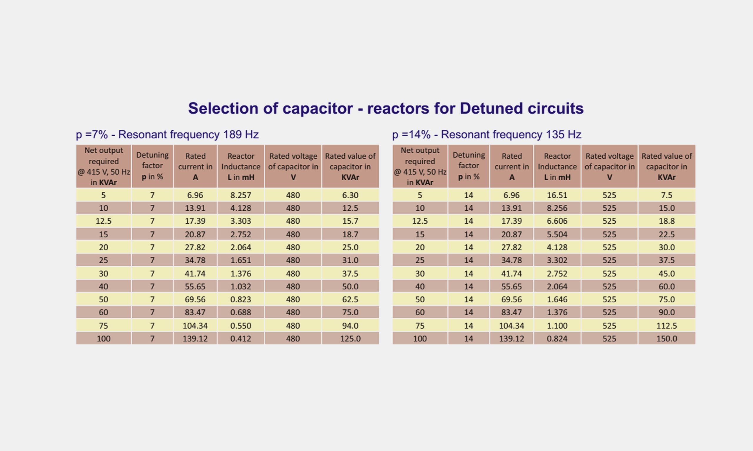
Capacitor-Reactor Matching Selection Table (Sourced: powerquality)
The filter reactor is a voltage boost for your capacitors. When the filter reactor is in series with capacitors, it may push the actual voltage higher at the capacitor terminals. So you can not pair a 400V capacitor with a reactor on a 400V network.
Standard Matching Rule:
7% Reactor (189 Hz): On a 400V net, voltage rises to ~430V, then 440V capacitors must be utilized.
14% Reactor (134 Hz): On a 400V net, voltage rises to ~465V, then 525V capacitors must be utilized.
12. How do you calculate total RMS current under severe harmonic conditions?
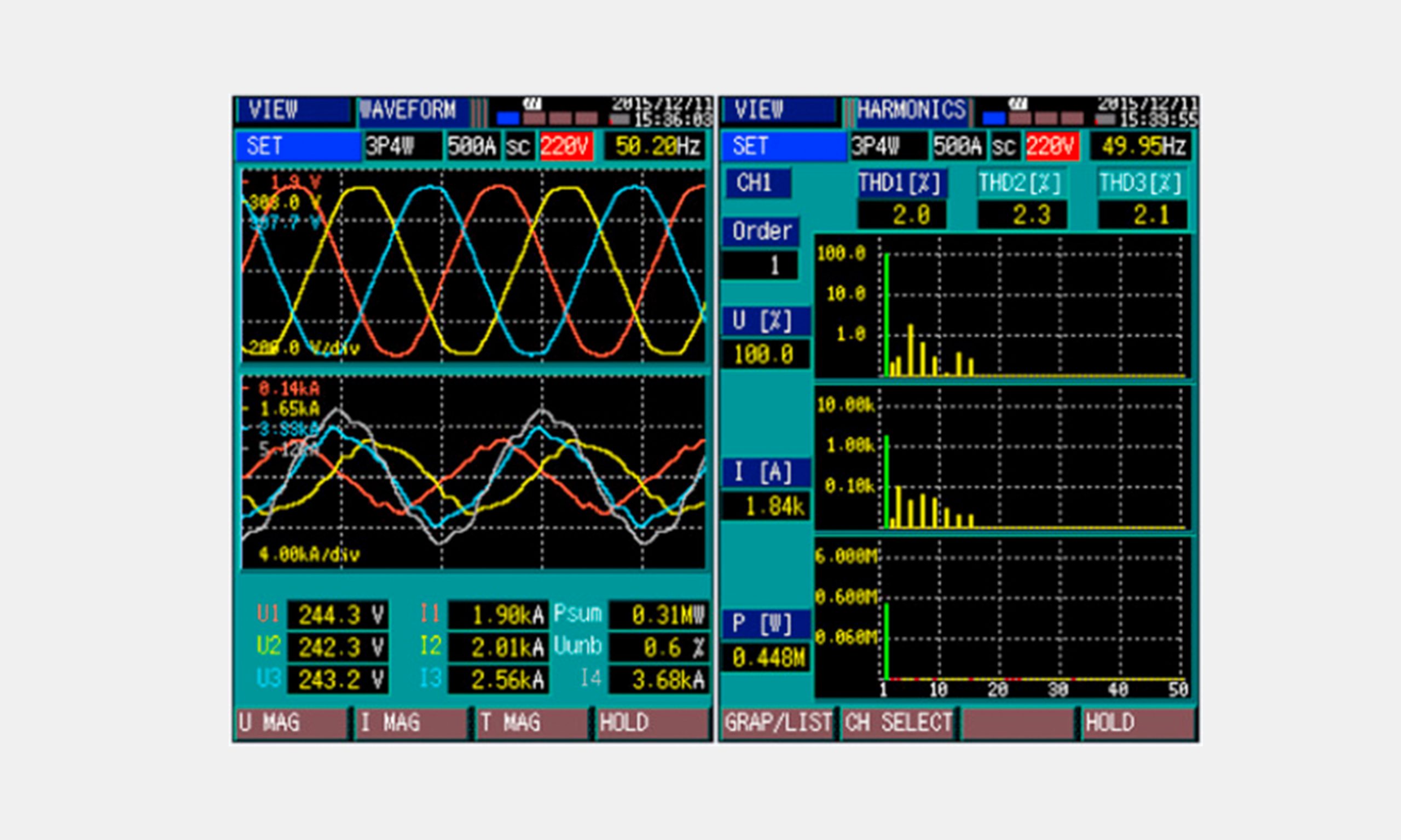
Real-time current waveform distortion and harmonic spectrum display (Sourced: sciencedirect)
In modern industrial grids with heavy non-linear loads (VFDs, rectifiers, arc furnaces), it is necessary to calculate the total effective RMS current. To prevent thermal overload:
$$I_{rms} = \sqrt{I_1^2 + I_3^2 + I_5^2 + I_7^2 + \dots + I_n^2}$$
Why Total RMS Current Matters?
Under-Sized Disasters: Choosing a filter reactor based solely on fundamental current is a dangerous shortcut, and it may lead to rapid thermal buildup and insulation breakdown.
13. Why is a thermal protection switch mandatory, and how should reactors be installed in crowded panels?
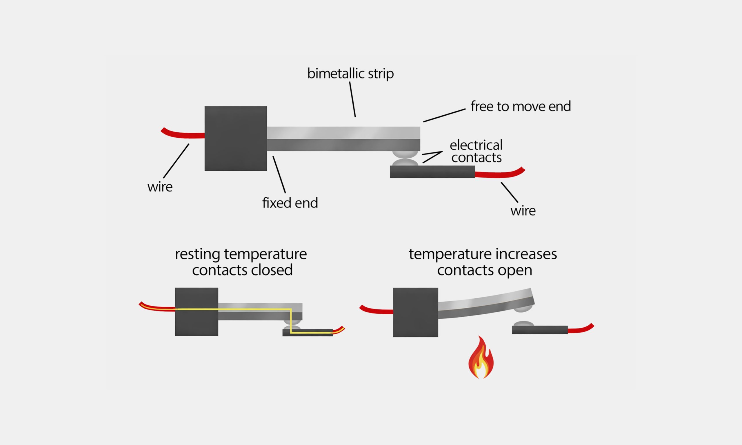
Working Principle of the Integrated Normally Closed (NC) Thermal Protection Switch (Sourced: allelcoelec)
To protect your equipment from extreme grid surges, thermal protection is mandatory.
Integrated NC Thermal Switch (120℃/135℃)
Built directly inside the center winding coil, the switch can instantly open if internal temperatures exceed 120℃ or 135℃. Then, your reactor will be automatically disconnected before insulation melting and fire hazards.
Panel Ventilation
To ensure you the best cooling inside panels, you can follow the steps below.
Vertical Air Flow: Make sure your reactors are all mounted vertically for internal cooling with natural airflow.
Maintain Breathing Space: Always keep your cables and adjacent components at a safe distance.
Avoid Harsh Environments: Keep your reactors away from corrosive fumes, heavy salt spray, or direct condensation.
Conclusion:
It is critical to choose the right filter reactor for your plant’s power quality and efficiency. To optimize power factor correction and eliminate unexpected downtime, you can explore our filter reactors for robust, high-linearity solutions. Reach out to our engineering team now with your specifications and projects.