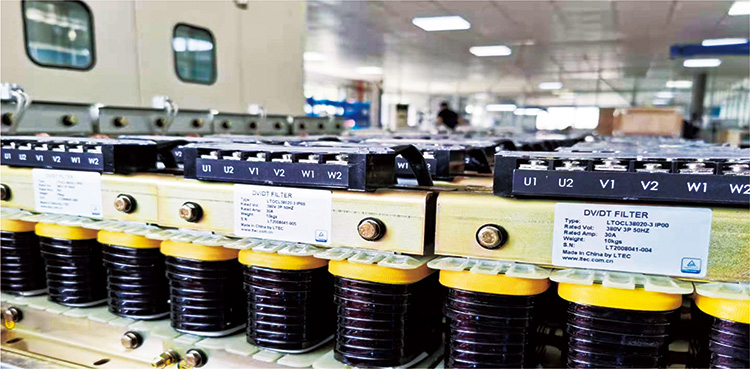
To improve industrial energy efficiency, more and more global manufacturing plants now apply adjustable frequency drives (AFDs/VFDs) and high-speed IGBTs (Insulated Gate Bipolar Transistors). However, those switching technologies also bring high-frequency harmonics and extremely high voltage change rates (dv/dt).
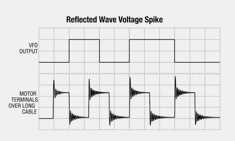
Long-running cables also bring the “reflected wave phenomenon.” The severe voltage spikes at both the inverter and motor terminals will cause insulation breakdown and costly motor winding failures.
So, understanding dv/dt filter reactors and knowing how to protect critical capital equipment is essential for you.
As a specialized inductive device installed between the VFD output terminals and the motor, the dv/dt filter reactor is widely used to control high voltage gradients and smooth rapid electrical transitions.
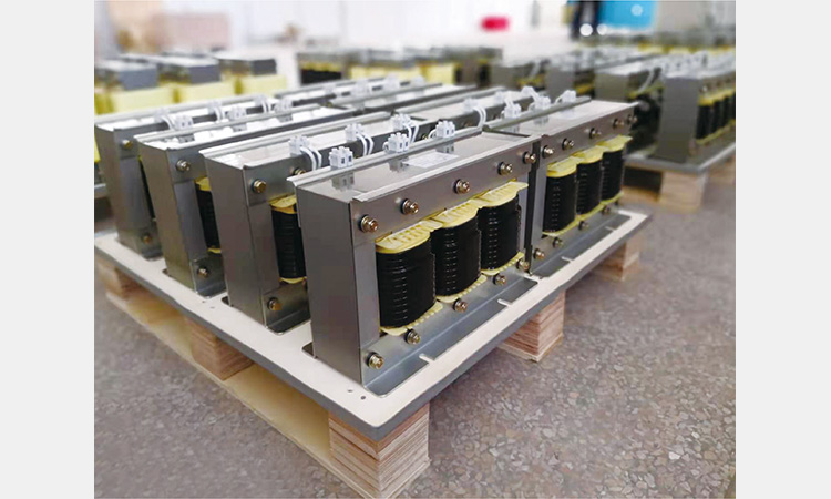
Core Construction Features
- Three-phase iron core for high linearity.
- Do not saturate even under heavy transient overloads.
Working Principle
- Introducing a controlled amount of inductive reactance into the output circuit.
- Then slowing down the voltage rise rate.
- Keeping the dv/dt well within safe thresholds (typically below $500\text{ V}/\mu\text{s}$).
Before learning about the dv/dt filter reactor, let’s check out the physical challenges created by modern VFD output waveforms:
Ultra-Fast IGBT Switching Dynamics
Creating ultra-fast transient voltage pulses that travel down the motor cables, modern IGBTs now switch at speeds up to $8000\text{ V}/\mu\text{s}$.
The Reflected Wave Phenomenon
If the cable lengths exceed critical thresholds (typically over 20 feet or tens of meters), the impedance mismatches cause the pulse to reflect toward the drive. In the end, there are high-amplitude standing waves and voltage spikes.
Severe Equipment Impact
Insulation Breakdown: The repeated high-voltage stress harms motor coil insulation. In the end, it leads to partial discharges and premature winding failure. To get rid of these risks and failures, you can choose VFD harmonic filters or output reactors.
Thermal Stress: Harmonics bring heat and noise.
Bearing Damage: Discharging through motor bearings, the capacitive currents cause fluting and premature bearing failure.
Protecting the entire motor drivetrain, deploying a dv/dt filter reactor can deliver:
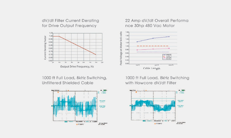
Mitigating Voltage Rise Rates (dv/dt)
Dampening voltage steps, the filter reactor relieves sensitive motor winding insulation.
Limiting Terminal Peak Voltages
Suppressing voltage peaks under safe operating limits, below 1000V for system voltages under 575V.
Enhancing Operational Reliability
Lowering high-frequency harmonic losses and thermal stress, the dv/dt filter reactor helps extend your motor lifespans and reduce equipment downtime.
Suppressing Electromagnetic Interference (EMI/RFI)
By smoothing out output waveforms, it minimizes high-frequency noise. For those problems, you can explore our advanced sine wave filters.
How to maximize the dv/dt filter reactor’s effectiveness? Here are the guidelines for your reference.
Carrier Frequency Alignment
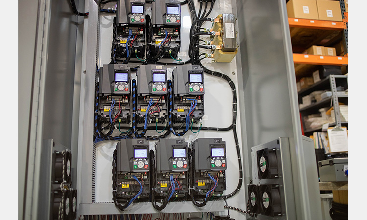
VFDs always prefer to run at high default carrier frequencies like 12 kHz. If you install a dv/dt filter reactor, it is better to change and lock the VFD’s carrier frequency. It will make it easy to fit within the reactor’s safe operating range, normally running between 2 kHz and 4 kHz.
Managing Cable Length and Sizing
Never make motor cables extra large to avoid voltage drop. If you use oversized cables, it will greatly increase stray capacitance and common-mode currents. In the end, the stress can overheat the reactor core.
Proper Physical Installation
Make sure that the reactor is as close as possible right next to the output terminals of the VFD.
Leave enough space for proper airflow (such as keeping at least a 100 mm clearance at both the top and the bottom).