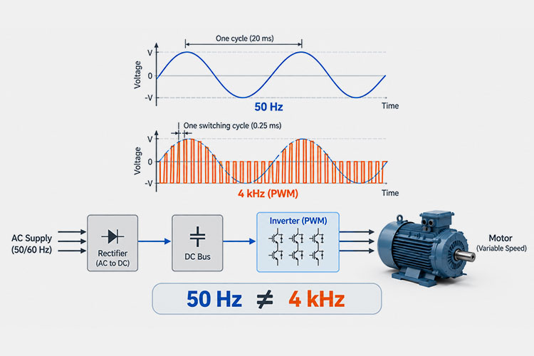
Comparison of VFD fundamental frequency versus PWM switching frequency
Ever tangled up in VFD frequencies? It happens to the best of us! While they work together to power your motor, they play completely different roles.
Meet the fundamental frequency—think of it as the steady heartbeat. It directly sets your motor’s speed and rhythm. Then there’s the switching frequency (or carrier frequency)—the lightning-fast pulse behind the scenes that tells the drive’s internal switches how rapidly to chop the power.
For example, your drive might cruise at a 50 Hz speed while switching at a brisk 4 kHz.
Getting this relationship right isn’t just about textbook theory. It’s the secret sauce to keeping motors quiet, cutting down energy loss, protecting your cables, and picking the right output filter for a rock-solid, long-lasting system!
1. VFD Fundamental Frequency vs. Switching Frequency: Quick Comparison
The main difference between VFD fundamental frequency and switching frequency is their function.
Fundamental Frequency
Switching Frequency
What it represents
Fundamental component of the VFD output
Rate at which the inverter’s power switches operate
Also associated with
Motor/output frequency
Carrier frequency or PWM frequency
Typical example
50 Hz
4 kHz
Main purpose
Establishes the motor’s operating electrical frequency
Creates the PWM output waveform
Controls motor speed?
Yes, it is a primary factor
Not directly
Typical frequency level
Usually tens of Hz in standard motor applications, but application-dependent
Usually several kHz, depending on the VFD
Motor audible noise
Related mainly to operating speed/load conditions
Can be strongly affected by switching-frequency selection
VFD switching losses
Not the primary setting
Higher switching frequency generally increases switching losses
dv/dt and cable effects
Not the primary cause
Important to consider with PWM edge characteristics and system design
Output filter selection
Important design parameter
Important design parameter
A simple way to remember the difference is:The fundamental frequency tells the motor how fast the rotating magnetic field should operate; the switching frequency tells the VFD how often to switch its inverter devices while synthesizing the PWM output.
2. What Is the Fundamental Frequency in a VFD?
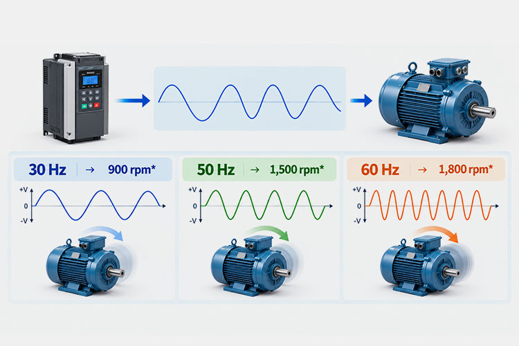
VFD fundamental frequency and speed control
The fundamental frequency in a VFD is the lowest-frequency component of the inverter output waveform that produces the motor’s intended rotating magnetic field. It is the frequency primarily associated with the motor’s operating speed.
Unlike a motor connected directly to a fixed 50 Hz or 60 Hz power supply, a VFD can vary this fundamental output frequency to control motor speed. For example, the drive may operate a motor at 20 Hz, 40 Hz, 50 Hz, or 60 Hz depending on the required operating condition.
3. How Does Fundamental Frequency Control Motor Speed?
For an AC induction motor, the synchronous speed of the rotating magnetic field is determined by the fundamental frequency and the number of motor poles:
Ns = 120f / P
Where:
Ns = synchronous speed in rpm
f = fundamental frequency in Hz
P = number of motor poles
For a four-pole motor, the relationship is straightforward:
Fundamental Frequency
Synchronous Speed
30 Hz
900 rpm
40 Hz
1,200 rpm
50 Hz
1,500 rpm
60 Hz
1,800 rpm
4. How Is Fundamental Frequency Related to V/Hz?
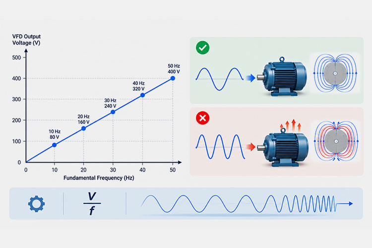
V/Hz control relationship and its impact on motor magnetic flux and thermal performance
Frequency cannot always be considered independently of voltage.
In conventional V/Hz (V/f) control, the VFD adjusts output voltage along with fundamental frequency to maintain an appropriate voltage-to-frequency ratio over the motor’s normal operating range.
For example, simply reducing frequency while maintaining an unsuitable voltage can increase magnetic flux and potentially contribute to motor heating or magnetic saturation. The exact voltage-frequency relationship depends on the motor, VFD control method, load, and operating range.
For this reason, the fundamental frequency is not merely a “speed setting”—it is part of the motor’s overall electromagnetic operating condition.
5. Is VFD Fundamental Frequency the Same as Grid Frequency?
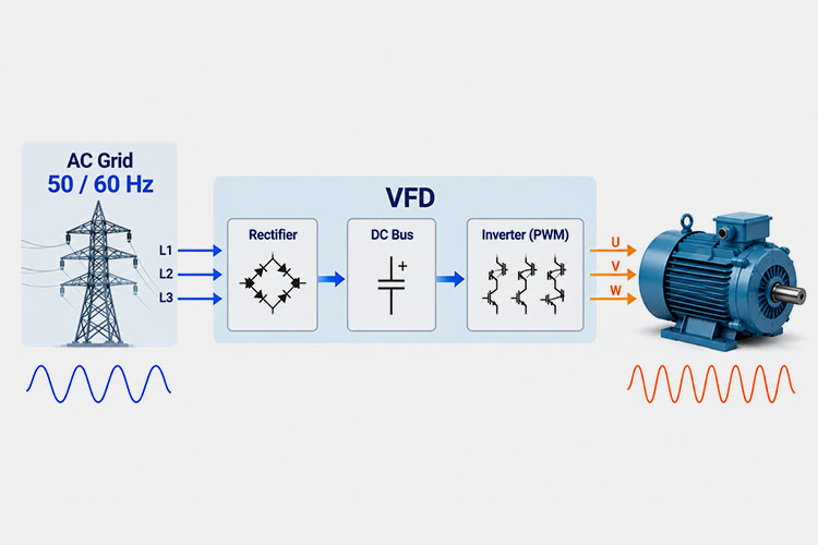
The incoming grid frequency is normally fixed—for example, 50 Hz or 60 Hz—while the VFD’s fundamental output frequency can be varied according to the required motor operating speed. For more background on regional grid frequency and equipment considerations, see 50 Hz vs. 60 Hz power systems.
Vfd grid frequency vs output frequency path.jpg
A simplified power path looks like this:
50/60 Hz AC Supply → Rectifier → DC Bus → Inverter/PWM → Variable Fundamental Output → Motor
The rectifier and DC bus decouple the motor-side output frequency from the fixed input grid frequency. As a result, a VFD supplied from a 50 Hz grid can, within the drive and motor’s permitted operating range, produce a fundamental output frequency that is different from 50 Hz.
This distinction between grid frequency and VFD output frequency is important when selecting motors, drives, reactors, and filters for variable-speed systems.
6. What Is Switching Frequency in a VFD?
The switching frequency in a VFD is the rate at which the inverter’s power semiconductor devices—commonly IGBTs in many conventional drives—switch on and off to generate a pulse-width-modulated (PWM) output voltage.
Switching frequency is much higher than the fundamental frequency. While a motor may operate with a fundamental frequency of 50 Hz, the inverter may switch several thousand times per second. A switching frequency of 4 kHz, for example, corresponds to approximately 4,000 switching cycles per second.
The exact available switching-frequency range depends on the VFD design, power rating, control method, and manufacturer. It should therefore be treated as a drive-specific setting rather than a universal fixed value.
7. What Happens When You Change the VFD Switching Frequency?
Changing your VFD’s switching frequency won’t change your motor’s speed, but it completely shifts how your drive and motor behave as a team!
Cranking it up brings a quieter motor and smoother current, but cooks up extra heat inside your drive. Turning it down cools things off and slashes losses, but wakes up that annoying motor hum.
Because of this constant give-and-take, higher isn’t always automatically better. Finding that sweet spot is a careful balancing act—it depends on your specific drive, motor, load, cable length, operating temperature, noise limits, and any filters you’ve got installed!
8. What Happens at a Higher Switching Frequency?
Cranking up your switching frequency quiets that annoying motor hum and smooths out current waves.
But there is a catch: more frequent switching cooks up extra heat and energy losses inside your drive. Because of this thermal burden, manufacturers often require you to derate your output current. Plus, it wakes up high-frequency side effects like EMI, common-mode noise, and tougher demands on your motor insulation and filters!
9. What Happens at a Lower Switching Frequency?
Dropping your switching frequency gives your VFD a breather by cutting heat and losses. The catch? Your motor gets noisier!
Higher vs. Lower VFD Switching Frequency
Higher Switching Frequency
Lower Switching Frequency
Motor audible noise
Generally lower
Generally more noticeable
Motor current ripple
Generally lower
Generally higher
Semiconductor switching losses
Higher
Lower
VFD heat generation
Higher
Lower
Potential drive derating
More likely
Less likely
High-frequency effects
Require greater attention
Generally reduced, but system-dependent
EMI considerations
Can become more significant
Generally less demanding
Output filter compatibility
Must be checked
Must also be checked
Always check the VFD manufacturer’s permitted carrier-frequency range and any required current derating before changing the setting.
10. How Do VFD Switching Frequency, dv/dt, Motor Cables, and Insulation Interact?
Unlike a smooth grid supply, a VFD delivers high-frequency pulses that spark unique electrical stress on your motor—think steep voltage jumps, long-cable reflections, and heavy insulation wear.
To untangle this, it helps to clear up a common mix-up: switching frequency and dv/dt are completely different beasts!
Switching Frequency: Measures how often your drive’s switches flip per second.
dv/dt: Measures how lightning-fast the voltage changes during a single switch. For a deeper explanation of output-side voltage stress and mitigation, see our dv/dt filter reactor guide.
Because of this, cranking up your carrier frequency doesn’t automatically mean your dv/dt spikes by the same proportion. The voltage stress hitting your motor terminals is a total team effort—shaped by pulse rise times, DC-bus voltage, inverter design, cable length, and motor impedance all together!
11. When Do You Need an Output Reactor, dv/dt Filter, or Sine Wave Filter?
When VFD voltage pulses stress your motor, you need output-side protection. Choosing the right shield isn’t just about cable length or switching frequency—it requires a complete system evaluation.
Here is your protection toolkit:
Output Reactor: Great for moderate conditioning. It slows down voltage transitions, though it doesn’t turn the output into a sine wave. Warning: Never use a standard input reactor on the output side unless it’s specially built for inverter harmonics.
dv/dt Filter: Specifically built to tame steep voltage spikes and rise rates. The voltage stays pulse-shaped, but insulation stress is drastically reduced.
Sine Wave Filter: The ultimate smooth operator. It uses an LC low-pass filter to make the motor voltage nearly sinusoidal, slashing acoustic noise and protecting sensitive or long-cable setups.
The golden rule is always to match your filter to your specific drive, motor, and system limits!
12. Which VFD Output Solution Should You Consider?
Application Concern
Solution to Evaluate
Moderate PWM output conditioning
Output reactor
High dv/dt at motor terminals
dv/dt filter
Reflected-wave / insulation stress
dv/dt filter or appropriate output filtering
Near-sinusoidal motor voltage required
Sine wave filter
Switching-related motor noise needs substantial reduction
Sine wave filter
Older or sensitive motor insulation
dv/dt or sine wave filter, depending on system requirements
Long VFD-to-motor cable
Evaluate dv/dt or sine wave filtering based on drive and cable specifications
There is therefore no universal rule such as “short cable = reactor, medium cable = dv/dt filter, long cable = sine wave filter.” Cable length is important, but the correct solution depends on the complete VFD–filter–cable–motor system.
Before selecting an output filter, verify at minimum the VFD voltage and current, motor rating, cable length, motor insulation requirements, switching-frequency range, maximum output frequency, and filter compatibility.
13. How Do You Choose the Right VFD Switching Frequency?
There is no universal “best” switching frequency. While cranking it up quiets motor hum, it ramps up drive heat. Dropping it keeps things cool, but increases noise.
To find the sweet spot:
Check the Manual: Always follow the manufacturer’s limits and derating rules.
Balance Heat vs. Noise: Match your acoustic needs with the drive’s thermal limits.
View the Whole Chain: Account for cable length and motor insulation stress.
Verify Filters: Ensure your switching frequency matches any installed output reactors or filters.
The goal isn’t the highest number, but a rock-solid, balanced system!
14. VFD Switching Frequency Selection Checklist
Before changing the carrier-frequency setting, check:
Parameter
Why It Matters
VFD model and rating
Determines allowable switching-frequency range
Motor rating and type
Affects drive and insulation requirements
Motor load
Determines required output current
Motor cable length
Influences reflected-wave and high-frequency effects
Motor insulation
Determines tolerance to PWM voltage stress
Audible noise requirement
May favor a higher switching frequency
Drive temperature/cooling
Higher switching losses increase thermal demand
Required current derating
May limit usable drive output
EMI environment
High-frequency switching behavior must be considered
Output reactor/filter
Must be compatible with the selected switching frequency
The key principle is simple:
Do not choose a VFD switching frequency on the assumption that higher is always better. Choose a setting that satisfies the drive manufacturer’s requirements while balancing motor performance, acoustic noise, thermal limits, cable conditions, and output-filter compatibility.
Conclusion
Fundamental frequency sets your motor’s speed, while switching frequency dictates how fast your drive chops the PWM power. Tinkering with the switching frequency tweaks noise and heat, but higher isn’t always better—it’s a delicate balancing act for your whole system. When long cables or voltage stress start causing trouble, matching the right output reactor, dv/dt filter, or sine wave filter keeps your motor safe and running smoothly! Need Help Protecting Your Motor System?Choosing the right output reactor or filter doesn’t have to be a guessing game. Explore our high-performance power quality solutions at ltecpower or contact our engineering team today for expert sizing, custom specs, and reliable support to keep your drives running at their absolute best!
Frequently Asked Questions
Is VFD switching frequency the same as carrier frequency?
In most VFD applications, switching frequency and carrier frequency refer to closely related concepts and are commonly used interchangeably. They describe the high-frequency switching used by the inverter to generate the PWM output waveform. You may also see terms such as PWM frequency or PWM carrier frequency in drive documentation.
However, terminology and parameter definitions can vary between VFD manufacturers, so the manual for the specific drive should always be checked.
Does VFD switching frequency control motor speed?
No. VFD switching frequency does not directly control motor speed. Motor speed is primarily determined by the fundamental output frequency, together with the motor pole count and operating conditions.
For example, changing the switching frequency from 4 kHz to 8 kHz while maintaining a 50 Hz fundamental frequency does not double the motor speed. Instead, the change primarily affects PWM-related characteristics such as audible noise, switching losses, current ripple, and thermal performance.
Is a higher VFD switching frequency better?
Not necessarily. A higher switching frequency can reduce audible motor noise and current ripple, but it also generally increases semiconductor switching losses and VFD heat.
Depending on the drive, higher carrier-frequency settings may require current derating. Cable conditions, EMI, motor insulation, ambient temperature, and output-filter compatibility should also be considered. The best setting is therefore a balance between motor performance and overall system requirements.
What switching frequency should I use for a VFD?
There is no universal switching frequency that is correct for every VFD application. The appropriate setting depends on the VFD model, motor, load, cable length, motor insulation, ambient conditions, acoustic requirements, and any output filter installed.
Start with the VFD manufacturer’s recommended or default carrier frequency, then verify whether derating or other restrictions apply before changing it.
Does VFD switching frequency cause harmonics?
VFD switching produces high-frequency spectral components associated with the PWM waveform, but these should not be confused with the characteristic low-order input current harmonics produced by a conventional VFD rectifier.
For example, the 5th and 7th input current harmonics commonly associated with six-pulse rectifiers are an input-side phenomenon. Switching-frequency components occur primarily on the inverter output side.
This distinction is important because the mitigation methods are different: input reactors and VFD harmonic filters address input-side harmonic problems, while output reactors, dv/dt filters, and sine wave filters address different aspects of the VFD output waveform.
For input-side mitigation, an AC line reactor or DC choke may also be considered depending on the drive topology and harmonic requirements.
Struggling with transformer overheating or power quality issues? Discover the root causes of electrical harmonics, how non-linear loads distort waveforms, and explore advanced mitigation solutions—including active filters, detuned reactors, and VPI-insulated transformers—to protect your industrial infrastructure.
Navigating the differences between 50 Hz and 60 Hz power grids is essential for international equipment sourcing. This comprehensive guide breaks down the physics, history, and core engineering risks—such as motor speed drops and transformer magnetic saturation—while providing actionable solutions to keep your global machinery running safely.
Navigate VFD harmonic challenges with confidence. This guide compares AC Line Reactors and Harmonic Filter Reactors, helping you lower THDi and choose the right component to keep your operations running safely.
Struggling to choose between passive and active harmonic filters? This comprehensive engineering guide breaks down core differences, real-world application scenarios, IEEE-519 compliance, and total cost of ownership to help industrial buyers make the right choice.