What Is a Current Limiting Reactor and How Does It Protect Your Power System?
September 29, 2026 | By Chris Wang
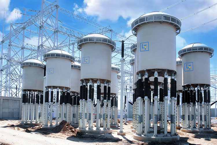
LTECPower outdoor current limiting reactor installation
A current limiting reactor (CLR) is a series-connected reactor that helps protect power systems by reducing prospective short-circuit current. It adds inductive reactance to the circuit, increasing fault-path impedance and reducing the fault current downstream equipment sees.
So, when does your power system need one, where should it be installed, and how do you select the right reactor? Let’s break it down.
1. What Is a Current Limiting Reactor?
A current limiting reactor is an inductive device connected in series with an electrical circuit to increase its reactance and limit the current that can flow during a short circuit.
Unlike a circuit breaker, the reactor does not interrupt the fault. Instead, it restricts the magnitude of the prospective fault current so that downstream equipment is exposed to a lower fault duty.
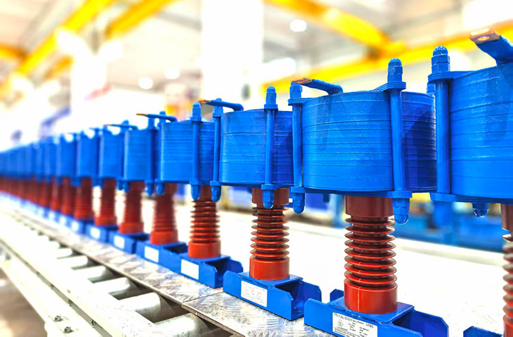
LTECPower factory indoor current limiting reactor assembly
This distinction is important:
| Device | Primary Function |
| Current Limiting Reactor | Limits the magnitude of fault current |
| Circuit Breaker | Interrupts and clears fault current |
Current limiting reactors are particularly relevant in medium-voltage and high-capacity distribution systems where available short-circuit current has become an equipment or system-design concern.
2. When Does a Power System Need a Current Limiting Reactor?
A current limiting reactor becomes worth evaluating when the available fault current is higher than desired for the equipment or system configuration.
You May Need a Current Limiting Reactor If:
Your Situation | Why It Matters |
Fault current approaches equipment ratings | Switchgear and other equipment may face excessive fault duty |
A new transformer is added | Additional source capacity can increase available short-circuit current |
Transformers operate in parallel | Parallel sources can increase the fault level |
A generator or new source is connected | The additional source may contribute fault current |
Plant or substation capacity is expanded | Existing equipment may have been selected for a lower original fault level |
Two bus sections are interconnected | Fault current can be contributed from both sides of the system |
A CLR should not be selected simply because the system is “large.” The first step is to determine the available fault current through a short-circuit study and compare the results with the applicable equipment ratings.
3. How Does a Current Limiting Reactor Reduce Short-Circuit Current?
The basic principle is straightforward.
A simplified relationship for fault current is:
Isc ≈ V/Z
Where:
Isc = prospective short-circuit current
V = system voltage
Z = total impedance of the fault-current path
Without a reactor:
Ztotal = Zsource + Ztransformer + Zsystem
After adding a current limiting reactor:
Ztotal = Zsource + Ztransformer + Zsystem + Zreactor
The additional reactor impedance increases the total impedance seen by the fault.
Higher fault-path impedance → Lower prospective short-circuit current
This is the fundamental operating principle of a current limiting reactor. Distribution-system studies have shown that series reactors effectively reduce calculated short-circuit current.
4. Where Is a Current Limiting Reactor Installed?
The location of the reactor determines which part of the system receives the fault-current-limiting effect.
Common configurations include:
Feeder Reactor
Bus → Current Limiting Reactor → Feeder → Load
Used to limit fault-current contribution into an individual feeder.
Bus-Tie Reactor
Bus A → Current Limiting Reactor → Bus B
Used between bus sections to limit fault-current transfer and help localize the effect of a fault on either bus.
Transformer Circuit
Transformer → Current Limiting Reactor → Distribution Bus
May be considered where the transformer/source contribution produces an excessive downstream fault level.
Generator or Source Connection
Generator / Source → Current Limiting Reactor → Bus
May be used where an additional source contributes excessive fault current to the common system.
Feeder and bus-tie reactors are established current-limiting applications, and the best installation point depends on where fault-current reduction is actually required.
5. What Does a Current Limiting Reactor Protect?
High short-circuit currents create both thermal and mechanical stresses in electrical equipment.
By reducing the prospective fault-current magnitude, a properly engineered current limiting reactor can reduce the fault duty imposed on equipment downstream of the reactor, including:
- Other downstream distribution equipment
This does not mean the reactor prevents the fault from occurring.
Its purpose is to control the magnitude of current during the fault until the protection system isolates the affected circuit.
Series current-limiting reactors themselves must also be designed for the thermal and mechanical short-circuit duty they may experience.
6. More Reactance Is Not Always Better
If additional reactance reduces short-circuit current, it may seem logical to simply use as much reactor impedance as possible.
That is not good engineering practice.
The reactor remains in the power circuit during normal operation, so its impedance can also affect normal system performance.
Increasing Reactor Impedance Can… | But May Also… |
Reduce prospective fault current | Increase voltage drop |
Reduce downstream fault duty | Affect voltage regulation |
Reduce short-circuit stress | Affect motor starting or large-load performance |
Help control system fault level | Add losses and other system-design considerations |
This is why reactor selection should begin with the system study rather than with an arbitrary impedance percentage.
7. Air-Core vs. Iron-Core Current Limiting Reactors
Core construction is particularly important in fault-current-limiting applications because the reactor must maintain sufficient reactance when current rises sharply during a fault.
Air-Core Current Limiting Reactor
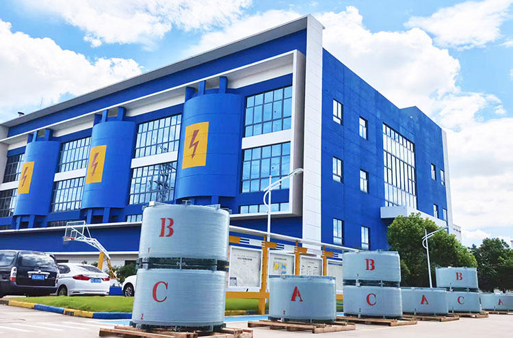
LTECPower air core current limiting reactor yard
An air-core reactor has no ferromagnetic core and therefore avoids magnetic-core saturation. This allows its inductance/reactance characteristics to remain more predictable at high fault currents.
For this reason, air-core construction is widely associated with current-limiting applications.
Iron-Core Current Limiting Reactor
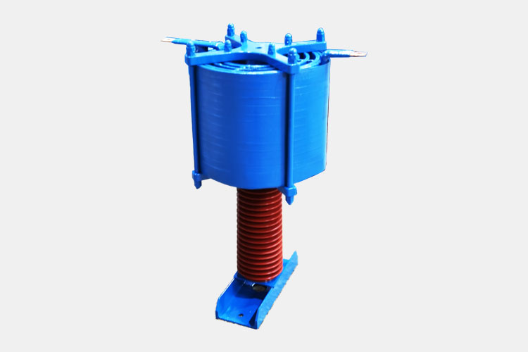
LTECPower iron core current limiting reactor
Iron-core designs can also be engineered for current-limiting applications, including designs that use air gaps to increase the saturation level. However, magnetic saturation must be considered carefully because loss of effective inductance during high-current conditions would reduce the desired current-limiting effect.
Design Factor | Air-Core | Iron-Core |
|---|
Inductance under high current | Not affected by core saturation | Depends on magnetic design |
|---|
External magnetic field | Requires installation clearance consideration | Depends on core/construction |
|---|
Selection | Application-specific | Application-specific |
|---|
The choice should be based on voltage, rated current, required reactance, fault duty, installation space, magnetic clearance, environment, and project requirements rather than core type alone.
8. How Do You Select a Current Limiting Reactor?
A current limiting reactor cannot be selected from system voltage alone.
The manufacturer needs to understand both the normal operating condition and the fault duty the reactor must withstand.
Before Requesting a Current Limiting Reactor, Prepare:
Parameter | Why It Matters |
System voltage | Determines system and insulation requirements |
Rated continuous current | Determines continuous current capability |
System frequency | Typically 50 Hz or 60 Hz |
Existing short-circuit current | Defines the present fault level |
Target short-circuit current | Defines the required current limitation |
Required reactance/impedance | Used when already determined by the system study |
Short-time current and duration | Defines thermal and mechanical fault duty |
Insulation level / BIL | Required for insulation coordination |
Indoor/outdoor installation | Affects mechanical and environmental design |
Ambient and installation conditions | Temperature, altitude, clearances, and enclosure conditions may affect design |
Short-circuit withstand is particularly important: series current-limiting reactors require defined thermal and mechanical short-circuit ratings, and the required duration should reflect the system protection and breaker clearing behavior.
If you do not yet know the required reactor impedance, provide the system information and short-circuit study data rather than estimating it.
9. Example: Plant Expansion Increases the Fault Level
Consider a factory with an existing medium-voltage distribution system:
Utility → Transformer → MV Bus → Loads
The original short-circuit level is within the ratings of the installed switchgear.
Later, the plant expands and adds another transformer or generation source:
Source 1 + Source 2 → MV Bus → Loads
The additional source contribution increases the available fault current at the bus.
If the calculated fault duty becomes too high for the intended system design, one engineering option may be to introduce additional series reactance at an appropriate location:
Source → Current Limiting Reactor → MV Bus
The reactor increases the impedance between the source and the fault, reducing the prospective short-circuit current seen downstream.
This does not mean a current limiting reactor is automatically the correct solution for every expansion project.
The required approach—and the reactor impedance, if one is used—should be determined from the actual network and short-circuit study.
10. Is a Current Limiting Reactor Right for Your System?
A current limiting reactor is designed for a specific type of electrical problem.
Consider Evaluating a CLR When:
✓ Available short-circuit current is too high
✓ System expansion has increased the fault level
✓ Existing equipment fault ratings are a concern
✓ Fault-current transfer between bus sections needs to be limited
✓ A system study identifies additional series impedance as an appropriate solution
A Current Limiting Reactor Is Not the Same Solution for:
✕ Harmonic distortion
✕ Capacitor-bank resonance
✕ Low power factor
✕ Reactive power compensation
✕ Every type of overcurrent problem
Those conditions may require different equipment such as harmonic filters, detuned reactors, power capacitors, or reactive power compensation systems.
The first step is therefore to identify the actual electrical problem before selecting the reactor.
Conclusion
Current limiting reactor selection depends on the complete power system, not simply the voltage or current printed on the nameplate.
For a technical evaluation, provide:
System Voltage
Rated Current
Frequency
Existing Short-Circuit Current
Target Fault Current
Required Reactance (if known)
Short-Time Current/Duration
Installation Conditions
LTECPower can evaluate the reactor requirements against your application and provide a current limiting reactor configuration based on the project parameters.
[View Medium Voltage Current Limiting Reactors]
[Request Technical Evaluation]
Frequently Asked Questions