
What Is a Volt-Ampere (VA) ?

September 7, 2026 | By Chris Wang

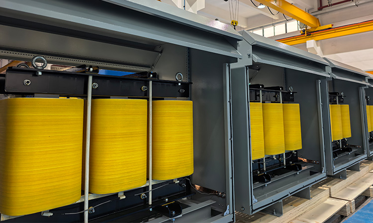
Row of ltecpower industrial dry-type transformers in a manufacturing facility
Precision-engineered LTECPower dry-type transformers undergoing final assembly

When you are managing a busy factory floor, what is the last thing you want? It might be a power failure. If you get the basic electrical calculations wrong, it may lead to costly shutdowns, ruined products, and expensive utility bills.

So learning how to design a reliable power system can be tough. However, LTECPower knows these struggles firsthand. As a Sino-German joint venture founded in 2004, we have spent over 20 years working alongside global leaders like GE, Siemens, ABB, and Schneider Electric in more than 60 countries.

Whether you are choosing dry-type transformers, setting up reactors, or dealing with harmonic issues, this guide will give you the practical formulas, engineering logic, and standards you need to keep your facility running smoothly. Follow it now!

 1. What Are Volt-Amperes (VA) and kVA? 

To design a safe power system, you need to understand how AC power works. They can be split into three main types:
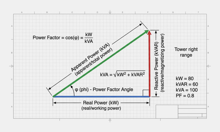
AC power triangle diagram illustrating the relationship between real power (kW), reactive power (kVAR), and apparent power (kVA)
The AC Power Triangle-sourced: viox

Real Power (kW)

The actual working energy that gets your things done, like running heavy motors or heating a furnace.

Reactive Power (kVAR)

The support energy needed to create and maintain magnetic fields in equipment like transformers and motors. It doesn’t do direct work, but your system needs it to function.

Apparent Power (kVA)

The combined total of real and reactive power. Think of it as the maximum total capacity your cables and transformers must be strong enough to handle.

2. Why Are Transformers Rated in kVA Instead of kW?

Industrial transformers are rated in kVA instead of kW because the heat and energy losses inside them depend completely on total voltage and current, not on how much actual work the load is doing. That is:

  • Core Losses: Caused by the magnetic field in the iron core and controlled by the applied voltage.
  • Coil Losses: Caused by electrical resistance in the winding coils and driven by the flowing current.

We cannot predict the exact Power Factor (PF) of your facility, and do not know how much actual power (kW) you will use. So a plant with simple heaters ($\text{PF} = 1.0$) puts a very different thermal load on the internal coils compared to a factory running heavy motors ($\text{PF} \le 0.8$). 

By rating equipment in kVA ($\text{Voltage} \times \text{Current}$), we set a clear, safe limit for heat and insulation so your equipment never overheats, no matter what kind of machinery you plug in.

3. How VFDs Multiply Thermal Stress?

Modern automation relies on Variable Frequency Drives (VFDs) to control motor speeds and save energy. However, VFDs draw power in sharp, fast pulses instead of smooth waves.
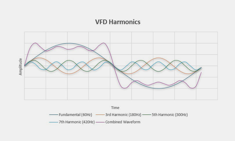
Electrical waveform diagram illustrating how fundamental and harmonic frequencies combine in VFD systems
The harmonic threat: VFDs draw pulsed currents-sourced: csemag

The Harmonic Threat

These pulses create high-frequency electrical harmonics that act like hidden heaters, causing extra eddy currents and wearing out standard transformers much faster.

The Smart Mitigation Path

Instead of wasting money by buying a much larger transformer just to absorb that extra heat, smart engineers fix the problem at the source. By installing custom AC reactors, passive harmonic filters ($\text{THDi} < 5\%$), or active harmonic filters right next to the VFDs, you protect your main transformer, smooth out the electrical current, and keep the power grid stable.

4. Meeting Global Standards and Engineering Compliance

A well-designed power system isn’t just about smooth operations. It also has to pass inspection and keep your facility out of regulatory trouble.
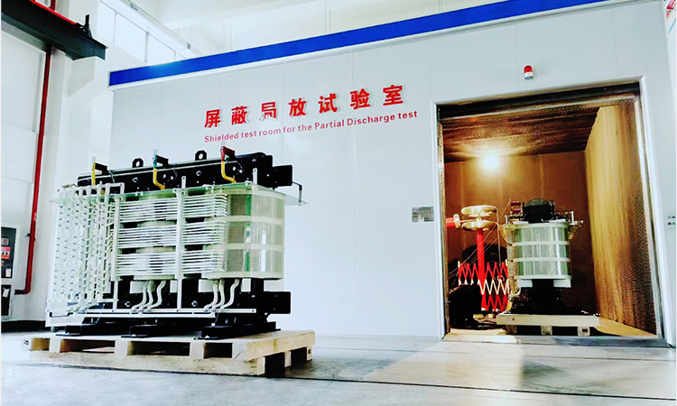
Industrial transformer undergoing partial discharge testing in a certified shielded laboratory at LTECPower
Every heavy-duty transformer and reactor undergoes rigorous testing in LTECPower factory

We know how frustrating utility disputes and safety checks can be, which is why at LTECPower, we take the guesswork out of compliance. Every component we build is engineered to seamlessly meet the highest global standards:

  • IEEE 519: Keeps your harmonic levels well within safe limits right where you connect to the public power grid.
  • IEC 60076 & IEC 61558-2-20: Ensures your dry-type transformers and reactors pass the strictest international tests for heat resistance and durability.
  • Certified Quality You Can Trust: Our entire manufacturing process is backed by ISO 9001 quality management and ISO 14001 environmental standards, alongside TÜV Rheinland, CE, and EAC certifications.

5. Essential Math for Engineers: How to Calculate VA, kVA, and Amps

 When you need to quickly check your system currents right on the shop floor, you don’t need complicated math. Just use these handy, standard engineering formulas to keep things safe and simple:

  • For Single-Phase Systems:$\text{Amps} = \frac{\text{VA}}{\text{Volts}}$ or $\text{Amps} = \frac{\text{kVA} \times 1000}{\text{Volts}}$
  • For Three-Phase Systems:$\text{Amps} = \frac{\text{kVA} \times 1000}{\text{Volts} \times \sqrt{3}}$ (where $\sqrt{3} \approx 1.732$)

6. 3-Phase kVA to Amps Quick Reference 

To save you time on calculations, we have mapped out the standard current loads below. Here is how typical transformer capacities translate to maximum amperage across different industrial voltage standards:
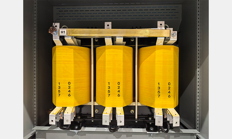
Dry-phase transformer high-voltage winding with H1 terminal in a metal enclosure manufactured by LTECPower
A precision-built dry-type transformer from LTECPower manufacturing facility

Transformer Capacity (kVA)

Max Amps @ 380V (3-Phase)

Max Amps @ 415V (3-Phase)

Max Amps @ 480V (3-Phase)

50 kVA

76 A

70 A

60 A

100 kVA

152 A

139 A

120 A

250 kVA

380 A

348 A

300 A

500 kVA

760 A

696 A

601 A

1000 kVA

1519 A

1391 A

1202 A

7. A Step-by-Step Sizing Walkthrough

Let’s walk through a real-world example to see how this works in practice. Imagine you need to size a transformer for a 75 kW industrial motor running on a 400V three-phase system, with a 0.85 power factor and a 20% safety margin for future facility expansion:

Step 1: Find the Apparent Power (kVA)

Divide your real power by the power factor ($\frac{75}{0.85}$), which gives you about $88.24\text{ kVA}$.

Step 2: Factor in Your Growth Margin

Multiply that result by $1.20$ to account for future load increases ($88.24 \times 1.20$), giving you roughly $105.89\text{ kVA}$. (In the real world, you’d round up to the next standard commercial size, like a $110\text{ kVA}$ or $125\text{ kVA}$ transformer).

Step 3: Check Your Full-Load Amps (FLA)

Plug your target capacity into our formula ($\frac{105.89 \times 1000}{400 \times 1.732}$) to confirm your system will be drawing around $152.8\text{ A}$ safely at full load.

8. How Poor Power Factor and Wrong Sizing Drain Your Budget?

Choosing equipment based solely on the lowest initial price is a gamble that usually ends up costing you more. When your power factor is low, local utilities have to push extra reactive power through the lines, which often leads to painful monthly penalty fees on your utility bill. Deploying reliable power capacitor banks and shunt reactors can immediately stabilize your reactive power.
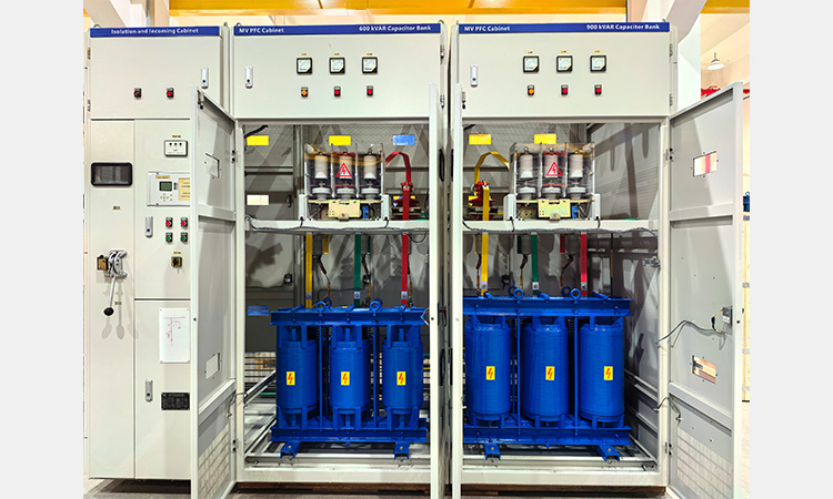
600 kVAR and 900 kVAR industrial power capacitor bank and reactor cabinets manufactured by LTECPower
Deploying high-performance power capacitor banks and shunt reactors from LTECPower

Beyond those fines, a poorly matched transformer eats away at your operating budget in two major ways:

  • No-Load Core Losses: Energy is constantly wasted 24/7 inside the iron core just to keep the transformer powered on, even when your factory is completely idle for the weekend.
  • Load-Dependent Copper Losses: If your transformer is too small for the job, it runs close to its thermal limit, creating heavy resistive heat losses that literally burn up extra electricity and drive up your power bills.
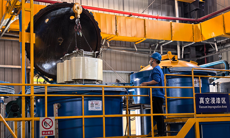
9. How Heat Destroys Your Transformer and How We Protect Against It

VPI vacuum pressure impregnation workshop facility for high-temperature insulation at LTECPower
Advanced VPI (Vacuum Pressure Impregnation) processing in LTECPower manufacturing facility

In heavy-duty power systems, heat is the hidden enemy that quietly burns out your equipment before its time. There’s a well-known engineering rule called the Arrhenius rule (or the 10°C rule) which shows that for every 10°C a transformer runs above its standard temperature rating, its lifespan is cut in half.

To protect your facility from sudden, costly hot-spot failures and unexpected downtime, every piece of transformer and reactor we build at LTECPower features certified Class H (180°C) and Class R (220°C) electrical insulation systems. 

Fully certified under UL-1446 (File No. E487892), these high-grade materials give your transformers the rugged resilience they need to handle heavy, shifting overloads without breaking a sweat.

10. How Does Your Transformer Survive Grid Surges and Short Circuits?

When unexpected grid disruptions happen, massive waves of fault current rush downstream. And a transformer’s short-circuit impedance (%Z) determines how well it absorbs that physical shock. Without rugged mechanical winding support inside, intense electromagnetic forces can tear the internal layers apart and cause complete equipment failure.
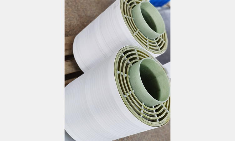
Advanced VPI (Vacuum Pressure Impregnation) processing in LTECPower manufacturing facility
Intense vacuum and pressure cycles force insulating varnish deep into every microscopic space from LTECPower

To make sure your operation stays up and running no matter what the grid throws at it, every transformer and reactor we build at LTECPower goes through uncompromising validation:

  • 1200 kV Lightning Impulse Testing: Tested right in our facility to ensure your equipment can handle extreme high-voltage surges from lightning strikes or grid switching.
  • Ultra-Low Partial Discharge Lab: Evaluated in our advanced, shielded laboratory, achieving a background partial discharge as low as 0.3 pC, proving our insulation design is airtight and built for the long haul.

11. Why VPI Technology Matters?

Many budget suppliers rely on traditional vacuum casting, which encases windings in solid epoxy resin. The catch is that under heavy daily temperature swings, tiny air pockets trapped inside that epoxy can expand and form dangerous hot spots that threaten your system.

Drawing on our deep Sino-German engineering roots, we do things differently at LTECPower by using advanced Vacuum Pressure Impregnation (VPI) technology instead:

Total Void Elimination

We use intense vacuum and pressure cycles to force premium insulating varnish deep into every microscopic space between the winding turns.

Proven Global Trust

From 13.8kV reactors powering GE facilities in Mexico to 34.5kV heavy-duty units built for ABB in Canada, our VPI-treated systems run cooler, dissipate heat much more effectively, and stand up strong against the toughest grid faults.

To learn more about how our manufacturing stands up against traditional methods, read our guide on transformer impregnation vs. encapsulation, or explore our heavy-duty harmonic mitigating transformers.

The Bottom Line 

Choosing the industrial electrical equipment like transformer and reactor is not just about checking boxes on a specification sheet or hunting for the lowest upfront price tag. It is a long-term investment in your plant’s safety, uptime, and profitability.

From avoiding painful utility power factor penalties and cutting down 24/7 core losses to protecting your facility against the silent killer of heat and sudden grid fault surges, every engineering detail matters.

Ready to future-proof your facility’s power infrastructure? Explore our comprehensive power quality systems or reach out to our engineering team today to discuss your next project or request a custom component review.

Frequently Asked Questions (FAQs)

1. How do I calculate the exact kVA required for a 3-phase industrial motor load?

Here is a quick, straightforward way to size your system: 

Take your motor’s active power in kilowatts, divide it by the power factor, and then add a 15% to 20% buffer to comfortably handle startup current spikes and future growth.

$$\text{kVA} = \frac{\text{kW}}{\text{PF}} \times 1.20$$

 In industrial environments where harmonics are present, detuned capacitor banks are your best bet. They correct the power factor, and because they are designed with integrated reactors, they will not amplify harmonic currents with cleaner power factor and no penalty surprises.

Variable frequency drives pull in choppy, pulsed currents that create high-order harmonics, leading to heavy eddy current losses. 

Under the Arrhenius rule, that extra internal heat cuts your transformer’s working lifespan in half unless you protect it using proper K-factor ratings or reliable line reactors.

Traditional vacuum casting traps air pockets inside solid epoxy, which can turn into dangerous hot spots over time. 

In contrast, our automated VPI (Vacuum Pressure Impregnation) systems at LTECPower force high-grade insulating varnish deep into every single winding turn. This eliminates hidden voids, giving your equipment much better heat transfer and rock-solid mechanical strength to keep your operations running safely.

Think of short-circuit impedance (%Z) as your system’s shock absorber. Getting this specification right keeps your voltage stable and makes sure your downstream switchgear can safely handle a sudden fault without twisting or destroying your internal windings.

Keep Learning

50 Hz vs 60 Hz Power Systems: Key Differences

Navigating the differences between 50 Hz and 60 Hz power grids is essential for international equipment sourcing. This comprehensive guide breaks down the physics, history, and core engineering risks—such as motor speed drops and transformer magnetic saturation—while providing actionable solutions to keep your global machinery running safely.

Leave a Reply

Your email address will not be published. Required fields are marked *